160
E300 Installation and Commissioning Guide
Issue Number: 1
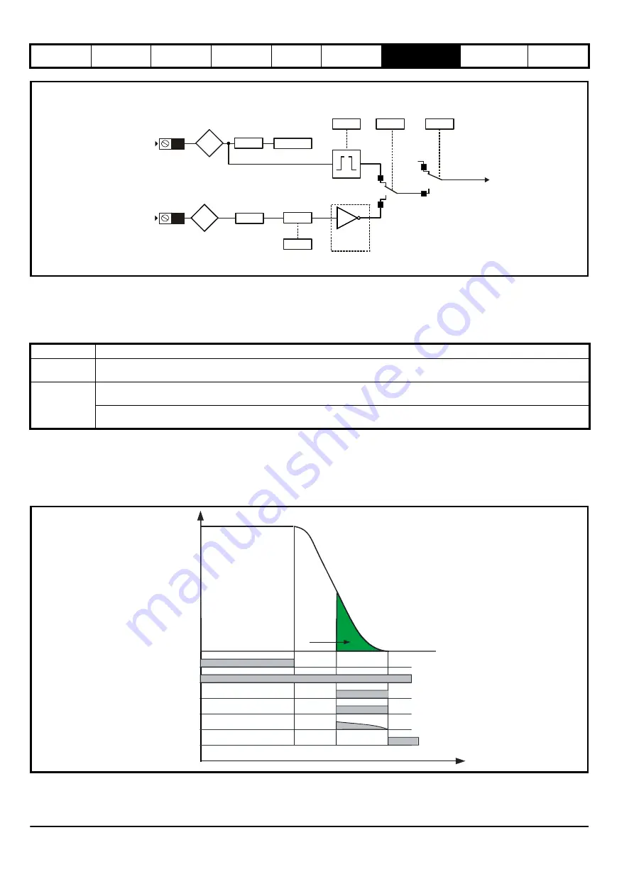
Figure 7-25 Floor sensor correction logic diagram
Floor sensor correction utilizes a feature of digital input 5, which bypasses the normal input logic resulting in a fast response to a change in the input
signal, such that when the sensor is activated the position is sampled in <1 µs. When digital input 5 is used for floor sensor correction, it is
recommended that the input is not used for any other purpose, and that Digital Input 5 Destination (
F22
) should be set to a value of 'A00'. It is possible
to specify whether the positive or negative edge of the floor sensor correction signal is detected using
Floor Sensor Correction Edge Detection
(
H25
).
Table 7-36 Floor Sensor Correction Modes
7.21.1 Floor sensor correction, direct to floor, on detection of signal via digital input 5
When the floor sensor correction signal is detected, travel within Floor Sensor Correction Target Distance (
G31
) is position controlled, modifying the
profile (deceleration and jerk rates) as required.
Once the floor sensor correction signal becomes active, the remaining controlled distance to the floor level is displayed in Remaining Floor Sensor
Correction Distance (
J47
). The speed at the point floor sensor became active is displayed in Speed At Floor Sensor Correction Active (
J46
).
Figure 7-26 Floor sensor correction direct to floor
Digital
Input 5
Creep to floor mode only
Creep to floor and direct to floor mode
Creep
Speed
Select
Digital
Input Y
Loss Of
Creep
Speed
Digital
Input Y
Invert
Digital
Input Y
Destination
Digital
Input Y
State
Digital
Input 5
Invert
Digital
Input 5
Destination
Floor Sensor
Correction
Edge Detection
Floor Sensor
Correction
Source
Select
Floor Sensor
Correction
Enable
Floor Sensor
Correction
Trigger
Digital
Input 5
State
T28
F16
H25
H24
H23
F22=A00
F07
Txx
G52
0
1
0
1
Profile
Floor Sensor Correction Mode
Direct to floor
Floor sensor correction is enabled via detection of the floor sensor correction signal connected to digital input 5. Travel within
Floor
Sensor Correction Target Distance
(G31)
is position controlled, modifying the profile as required.
Creep to floor
Floor sensor correction is enabled via detection of the floor sensor correction signal connected to digital input 5. Travel within
Floor
Sensor Correction Target Distance
(G31)
is position controlled, modifying the profile (deceleration and jerk rates) as required.
Floor sensor correction is enabled via de-selection of the creep speed reference. Travel within
Floor Sensor Correction Target
Distance
(G31)
is position controlled, modifying the profile (deceleration and jerk rates) as required.
Speed signals
Target
correction
distance
Deceleration rate (
)
G12
Deceleration and jerk controlled
by the profile generator to
stop within the target distance
Remaining distance
Floor sensor
Run jerk 3 (
)
G15
Floor sensor correction signal
Target distance
Floor sensor correction enable
Floor Sensor Correction Target Distance
(
)
G31
Control Terminal
28
Remaining Floor Sensor Correction Distance
(
)
J47
Floor Sensor Correction Enable
(
)
H23
Summary of Contents for E300 Series
Page 211: ......
Page 212: ...0479 0005 01 ...


