eloProg - Vers. 1.0
11
Instructions concerning connection cables
Î
Cables used for connections must be AWG26 - AWG14. Cables used for connections of
longer than 50m must have a cross-section of at least 1mm
2
(AWG16).
Î
We recommend the use of separate power supplies for the safety module and for other
electrical power equipment (electric motors, inverters, frequency converters) or other sources
of disturbance.
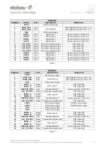
Connections of each unit are listed in the table below:
Master 485EPB
TERMINAL
SIGNAL
TYPE
DESCRIPTION
OPERATION
1 24VDC
-
24VDC power supply
-
2 MASTER_ENABLE1
Input
Master Enable 1
Input (
"type B"
according to EN 61131-2 )
3 MASTER_ENABLE2
Input
Master Enable 2
Input (
"type B"
according to EN 61131-2 )
4 GND
-
0VDC power supply
-
5 OSSD1_A
Output
safety output 1
PNP active high
6 OSSD1_B
Output
PNP active high
7 RESTART_FBK1
Input
Feedback/Restart 1
Input according to EN 61131-2
8 OUT_STATUS1
Output
Programmable digital output
PNP active high
9 OSSD2_A
Output
safety output 2
PNP active high
10 OSSD2_B
Output
PNP active high
11 RESTART_FBK2
Input
Feedback/Restart 2
Input according to EN 61131-2
12 OUT_STATUS2
Output
Programmable digital output
PNP active high
13 OUT_TEST1
Output
Short circuit detected output
PNP active high
14 OUT_TEST2
Output
Short circuit detected output
PNP active high
15 OUT_TEST3
Output
Short circuit detected output
PNP active high
16 OUT_TEST4
Output
Short circuit detected output
PNP active high
17 INPUT1
Input
Digital input 1
Input according to EN 61131-2
18 INPUT2
Input
Digital input 2
Input according to EN 61131-2
19 INPUT3
Input
Digital input 3
Input according to EN 61131-2
20 INPUT4
Input
Digital input 4
Input according to EN 61131-2
21 INPUT5
Input
Digital input 5
Input according to EN 61131-2
22 INPUT6
Input
Digital input 6
Input according to EN 61131-2
23 INPUT7
Input
Digital input 7
Input according to EN 61131-2
24 INPUT8
Input
Digital input 8
Input according to EN 61131-2
Table 2


