background image

SINUS/ISD

15P0082B8

6 - 23

6.4.1.12


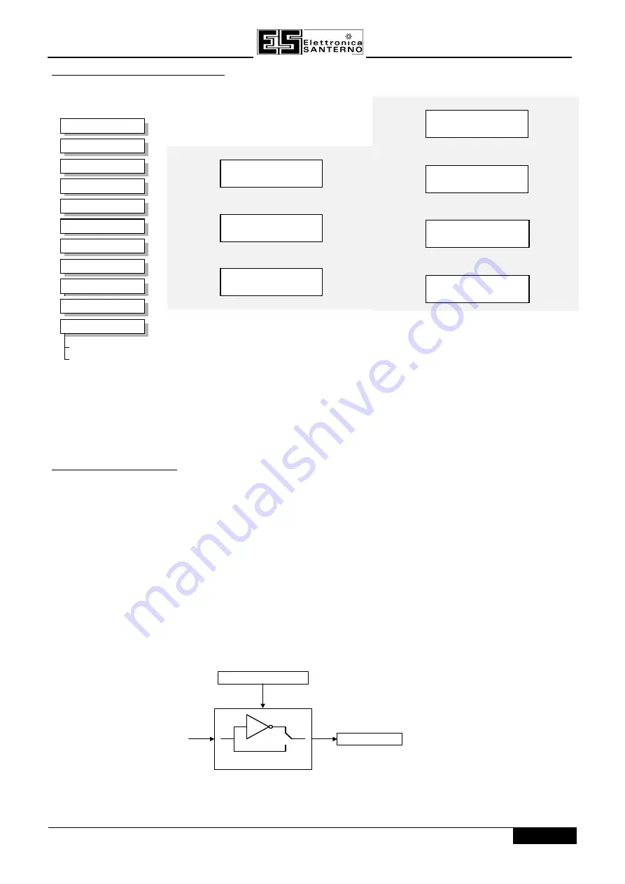
Functional Description

The Inverter has seven digital inputs. There is a DIGITAL INPUT function block associated with each of these:

DIGITAL INPUT 2 is associated with terminal 8
DIGITAL INPUT 3 is associated with terminal 9

DIGITAL INPUT 5 is associated with terminal 11
DIGITAL INPUT 6 is associated with terminal 16

The input electronics of the Inverter converts the input signal to a TRUE or FALSE logic value. The digital input
block takes this value and optionally inverts it before providing the VALUE output.

7

SETUP PARAMETERS

2

3

4

5

5

5

5

5

5

5

DIN 7 INVERT

Parameter Descriptions

INVERT

Range: FALSE / TRUE

VALUE

Range: FALSE / TRUE

INPUT

VALUE

INVERT

UNPROCESSED

DIGITAL INPUT 2

VALUE [ 34]

FALSE

FALSE – [ 33] INVERT

DIGITAL INPUT 4

VALUE [ 40]

FALSE – [ 39] INVERT

DIGITAL INPUT 6

VALUE [726]

FALSE – [725] INVERT

DIGITAL INPUT 1

DIGITAL INPUT 1

VALUE [ 31] –– FALSE

FALSE

[ 30] INVERT

––

DIGITAL INPUT 3

VALUE [ 37] –– FALSE

FALSE – [ 36] INVERT

DIGITAL INPUT 5

DIGITAL INPUT 5

[ 43] –FALSE

– [ 42]

––

DIGITAL INPUT 7

DIGITAL INPUT 7

VALUE [728] –FALSE

FALSE [727] INVERT

––

Summary of Contents for SINUS/ISD 200 S-0.75

Page 1: ...non original spare parts Elettronica Santerno reserves the right to make any technical changes to this manual and to the device without prior notice If printing errors or similar are detected the cor...

Page 2: ...DC and DC Should you replace a inverter inside the system and before starting operations again it is absolutely necessary to restore all pre set parameter values properly ATTENTION ATTENTION Non comp...

Page 3: ...h until the right value press E the message password unlocked is displayed now is impossible to access to the parameter view level inside the menu Menus and select according to requirements of program...

Page 4: ...THING REQUIREMENTS 3 1 14 3 1 2 1 Protective Earth PE Connections 3 1 14 3 1 2 2 EMC Earth Connections 3 1 14 3 1 3 CABLING REQUIREMENTS 3 2 14 3 1 3 1 Planning Cable Runs 3 2 14 3 1 3 2 Increasing Mo...

Page 5: ...4 7 4 1 Starting Several Inverters Simultaneously 4 13 14 4 7 4 2 Single Wire Logic Starting 4 13 14 4 7 4 3 Two Wire Logic Starting 4 14 14 4 7 4 4 Three Wire Logic Starting 4 14 14 5 0 5 0 THE OPER...

Page 6: ...n Mode 6 1 82 6 2 1 3 Programming Rules 6 2 82 6 3 6 3 EXECUTION RULES EXECUTION RULES 6 2 82 6 3 1 UNDERSTANDING THE FUNCTION BLOCK DESCRIPTION 6 3 82 6 3 1 1 MMI Menu Maps 6 3 82 6 3 2 HEXADECIMAL R...

Page 7: ...E AND REPAIR 8 1 8 1 ROUTINE MAINTENANCE ROUTINE MAINTENANCE 8 1 2 8 2 8 2 REPAIR REPAIR 8 1 2 8 2 1 SAVING YOUR APPLICATION DATA 8 1 2 8 2 2 RETURNING THE UNIT TO ELETTRONICA SANTERNO 8 1 2 9 0 9 0 S...

Page 8: ...13 3 13 3 USING MULTIPLE MOTORS ON A SINGLE INVERTER USING MULTIPLE MOTORS ON A SINGLE INVERTER 13 2 2 14 0 14 0 SERIAL COMMUNICATIONS SERIAL COMMUNICATIONS 14 1 14 1 CONNECTION TO THE P3 PORT CONNECT...

Page 9: ...company or to the supplier Should the supply be different from what you requested refer to the supplier at once Should you have to store the equipment before commissioning it make sure that the ambie...

Page 10: ...for the Operator Station where supplied Programming Operator Station or suitable PC programming tool only Programming Operator Station or suitable PC programming tool only Know your application insta...

Page 11: ...ation switches 5 5 Cooling fan Type B only 13 13 Power terminal shield Type A only 6 6 Gland plate 14 14 Power terminal shield Type B only 7 7 Standard front panel 15 15 Technology box interface conne...

Page 12: ...ramp rates Stopping Modes Ramp ramp with hold coast dc injection fast stop Ramps Symmetric or asymmetric ramp up and down rates Raise Lower Programmable MOP function Jog Programmable jog speed Logic...

Page 13: ...OR DRIVE CONV FREQUENCE VARIADOR ALTERNA Tag Tag American US American US P 50Hz P5 P 50Hz P5 P 60Hz P6 P 60Hz P6 LANGUAGE 1 ENGLISH 0 0 MAX SPEED 57 60 0Hz 50 0Hz 60 0Hz BASE FREQUENCY 106 60 0Hz 50 0...

Page 14: ...casing of the Inverter when the blank cover the Operator Station or the Technology Box option is removed These switches configure the analog i o terminals Refer to Chapter 6 Programming Your Applicati...

Page 15: ...e is interrupted to insert contactors etc re connect the screen using the shortest possible route Keep the length of screen stripped back as short as possible when making screen connections Ideally us...

Page 16: ...les close or parallel to the motor dc link and braking chopper circuit for any distance Never run supply dc link or motor cables in the same bundle as the signal control and feedback cables even if th...

Page 17: ...st be sufficiently immune The VSD and associated equipment are mounted onto a conducting metal mounting panel Do not use cubicle constructions that use insulating mounting panels or undefined mounting...

Page 18: ...e point for all signal and control cabling This may be further subdivided into an analogue and a digital reference busbar each separately connected to the star earthing point The digital reference is...

Page 19: ...okes transformers The cable between VSD and motor even when screened armoured Connections to external braking chopper and resistor even when screened armoured AC DC brushed motors due to commutation D...

Page 20: ...Maintain a minimum clearance for ventilation of 100 mm above and below Table 3 1 Mechanical Dimensions for SINUS ISD Type A Table 3 1 Mechanical Dimensions for SINUS ISD Type A W W 1 W 2 D H H 1 Heat...

Page 21: ...Inverter Be aware that other equipment may have its own clearance requirements When mounting two or more SINUS ISDs together these clearances are additive Ensure that the mounting surface is normally...

Page 22: ...namic Braking Circuit Figure 3 6 Dynamic Braking Circuit When the DC link voltage rises above 750V for the 400V build 385V for the 230V build the brake unit switches the external resistor network acro...

Page 23: ...for the application The minimum resistance of the combination shouldn t be less than that specified in subchapter 3 3 3 The resistor s must be specified to the maximum DC link voltage 810V for the 400...

Page 24: ...g is electrically isolated and cannot be made live unintentionally by other personnel Note Refer to Chapter 11 Technical Specifications for additional Cabling Requirements and Terminal Block Wire Size...

Page 25: ...Fault Monitoring Systems page 3 14 14 3 4 1 3 Power Wiring Connections 1 Remove the terminal cover retaining screws and lift off the terminal cover 2 Remove the internal power terminal shield 3 Feed...

Page 26: ...13 Typical Connection to the Control Terminals CONTROL TERMINALS CONTROL TERMINALS 1 1 0 V REF 0 V REF 2 2 Analog input 1 speed Analog input 1 speed 3 3 10 V REF 10 V REF 4 4 Analog input 2 speed tri...

Page 27: ...specified motor cable runs may suffer from nuisance overcurrent trips refer to Chapter 11 Technical Specifications Cabling Requirements for maximum cable lengths A choke may be fitted in the inverter...

Page 28: ...y EMC filter s internal capacitors which are connected between phase and earth This has been minimised in Elettronica Santerno s filters but may still trip out any circuit breaker in the earth system...

Page 29: ...sulation with a Meggar Check for damage to equipment Check for loose ends clippings drilling swarf etc lodged in the Inverter and system If possible check that the motor can be turned freely and that...

Page 30: ...erator Station Remote Remote Analog and digital inputs and outputs RS232 Port or the Technology Box Thus the Inverter can operate in one of four combinations of local and remote modes analogue and dig...

Page 31: ...time However you can fix either or both modes in software to be either Local or Remote control This makes the L R L R key inoperative for that mode In this way you can select a combination where both...

Page 32: ...nt is at zero Turn the speed potentiometer up a little to apply a small speed setpoint The RUN LED will light and the motor will rotate slowly Reverse the motor s direction of rotation either by press...

Page 33: ...ming tool It can be run in Sensorless Vector Fluxing mode or as a simple Open loop Inverter V F fluxing 4 5 1 QUICKSET UPASANOPEN LOOPINVERTER V FFLUXING By loading a different macro you are installin...

Page 34: ...sing inductance These parameters are set to a value depending on the overall power build e g 230V 0 75kW Table 4 Table 4 3 3 Important Parameters for the Sensorless Vector Fluxing Mode Important Param...

Page 35: ...r must be inserted the 90 of the value calculated with the above mentioned formulas LEAKAGE INDUC LEAKAGE INDUC The value corresponds to the 10 of the calculated mutual induc therefore this value must...

Page 36: ...han expected motor torque production Setting the value too high can cause the Inverter to enter current limit If this occurs the Inverter will be unable to ramp up in speed Reducing the value of STATO...

Page 37: ...JOG SETPOINT at a ramp rate set by JOG ACCEL RATE not shown in the diagram Release the JOG key to stop the Inverter Interaction between RUN and JOG Only one of these signals can be in effect at any o...

Page 38: ...grammed RAMP DECEL RATE time When this time has elapsed SPEED TRIM is ramped to 0 in the programmed STOP RATE time Note If SPEED TRIM does not operate SPEED DEMAND is reduced to 0 in RAMP DECEL RATE t...

Page 39: ...or COAST The stopping sequence starts when the FAST STOP input goes FALSE regardless of the state of the RUN input 4 7 2 2 Forced Coast Stop Using the Coast Stop mode immediately disables the power st...

Page 40: ...f stop logic are shown below SPEED DEMAND REMOTE SETPOINT Speed 0 RUN FWD STOP REMOTE SETPOINT RUN REV RUN FWD ignored as already running RUN FWD acted on immediately as previous state was RUN FWD RUN...

Page 41: ...is disabled regardless of the state of any other parameters In conjunction with the HEALTHY output parameter DRIVE ENABLE can synchronise several Inverters on power up 4 7 4 2 Single Wire Logic Start...

Page 42: ...en the push button contact is released causing RUN FWD to return to FALSE While the Inverter is running forwards the RUN REV parameter is ignored until the Inverter is stopped even though the RUN FWD...

Page 43: ...hapter contains information on how to customise the Operator Station to your application Below are some of the ways in which you can make the Operator Station work effectively for you Consider the fol...

Page 44: ...trip is no longer active LOCAL LOCAL REMOTE REMOTE R L Control Toggles between Remote and Local control for both Start Stop Seq and Speed Control Ref When toggling the display automatically goes to t...

Page 45: ...e State Requested direction and actual direction are forward Requested direction and actual direction are reverse Requested direction is forward but actual direction is reverse Requested direction is...

Page 46: ...etting up the Operator Station display PARAMETER SAVE Save the application SYSTEM contains all the parameters for the internal workings of the Operator Station including Macro selection Figure 5 Figur...

Page 47: ...LISATION FLUXING VECTOR FLUXING AUTOTUNE VOLTAGE CONTROL UNDERLAP COMP PATTERN GEN DYNAMIC BRAKING INJ BRAKING FLY CATCHING TRIPS STATUS I O TRIPS I T TRIPS STALL TRIP TRIPS HISTORY OP STATION PASSWOR...

Page 48: ...nd reverts the up and down keys to scrolling through the parameters A writable parameter may be non writable if it is the destination of a link In this case it will be indicated by appearing on the le...

Page 49: ...displayed i e OPERATOR or for example TRIPS Releasing the key clears the display and releases you into that menu WELCOME SCREEN OPERATOR PROG The Menu System M E SETPOINT REMOTE to other parameters t...

Page 50: ...menu in the PARAMETER SAVE menu at level 1 After saving press the PROG key to return to the previous display 5 4 7 3 Changing the Display Language Holding down the PROG PROG key at power up takes you...

Page 51: ...hen press the E E key until the Welcome screen is displayed 5 4 7 6 Quick Restore Default A special key combination restores to the Inverter the current product code default values and Macro 1 paramet...

Page 52: ...assword protected parameter it will cause an alert reason message to be displayed By default the password feature is disabled i e 0000 There are two password parameters stored in the PASSWORD menu at...

Page 53: ...pter 6 Programming Your Application OPERATOR MENU 5 5 5 1 Selecting a Startup Screen The STARTUP SCREEN parameter selects which of the OPERATOR MENU parameters will be used as the Startup screen Press...

Page 54: ...l 2 to display the UP FOR ACTION page Note Pressing the key as instructed restores to the Inverter the last saved parameter settings 5 6 3 COPYING AN APPLICATION The Operator Station is a programming...

Page 55: ...lication data stored in the Inverter as a safety measure Refer to Transferring Your Application to Another SINUS ISD Inverter above You can have the Operator Station back up the application each time...

Page 56: ...15P0082B8 USER MANUAL SINUS ISD 5 14 14...

Page 57: ...nsfers the value of an output parameter to an input parameter of another or the same function block Each individual block is a processing feature i e it takes the input parameter processes the informa...

Page 58: ...ically arranged for minimal delay The output value transferred by a link on execution is clamped to be between the maximum and minimum value for its destination input parameter If a links source and d...

Page 59: ...1 MMI Menu Maps The function block descriptions include an easy find menu showing the menu levels and titles encountered to find the appropriate menu title and the parameters contained in the menu s...

Page 60: ...t the same time then the trip codes are simply added together to form the value displayed Within each digit values between 10 and 15 are displayed as letters A to F For example if the ACTIVE TRIPS par...

Page 61: ...82 PASSWORD 6 45 82 AUTO RESTART 6 12 82 PATTERN GEN 6 46 82 AUTOTUNE 6 14 82 PID 6 47 82 BRAKE CONTROL 6 15 82 PRESET 6 49 82 COMMS CONTROL 6 16 82 RAISE LOWER 6 51 82 CURRENT FEEDBACK 6 17 82 REFERE...

Page 62: ...he output VALUE to be FALSE 10V 10V 0 30 100 0 FALSE 1 TRUE LEVEL TRUE FALSE VALUE raw input MMI Menu Map 1 SETUP PARAMETERS 2 FUNCTION BLOCKS 3 INPUTS OUTPUTS 4 ANALOG DIGIN 5 ANALOG DIGIN 1 5 ANALOG...

Page 63: ...The input voltage or current is converted to an equivalent percentage by the Inverter s analog input electronics The percentage generated by a given input voltage depends on the hardware range selecte...

Page 64: ...appear as a value of 0 00 Similarly an input equal to the high input range will appear as a value of 100 00 OFFSET OFFSET Range 300 00 to 300 00 An offset added to the input after the scaling factor...

Page 65: ...to 5V 4 to 20mA and 20 to 4mA An input break is defined as an input reading less than either 0 1V or 0 45mA When an input break has been detected the VALUE output is forced to be the BREAK VALUE Confi...

Page 66: ...TERS 2 FUNCTION BLOCKS 3 INPUTS OUTPUTS 4 ANALOG OUTPUT 5 ANALOG OUTPUT 1 AOUT 1 VALUE AOUT 1 SCALE AOUT 1 OFFSET AOUT 1 ABS AOUT 1 TYPE ANALOG OUTPUT 1 ANALOG OUTPUT 1 0 00 45 VALUE 100 00 46 SCALE 0...

Page 67: ...te TYPE parameter Table 6 Table 6 3 3 Select Output Signal Select Output Signal Figure 6 Figure 6 4 4 I O I O Configuration Switches Configuration Switches shown at Manufacturing defaults shown at Man...

Page 68: ...Determines the number of restarts that will be permitted before requiring an external fault reset INITIAL DELAY 1 INITIAL DELAY 1 Range 0 0 to 600 0 s Determines the delay for the first restart attemp...

Page 69: ...dicates that an auto restart is occuring ATTEMPTS LEFT ATTEMPTS LEFT Range xxxxx Indicates the number of attempts left before an external fault reset is required TIME LEFT TIME LEFT Range xxxx x s Whe...

Page 70: ...ndition The function block cannot be changed whilst the drive is running When the test is complete the stack is disabled and the motor left to coast MMI Menu Map 1 SETUP PARAMETERS 2 FUNCTION BLOCKS 3...

Page 71: ...r Descriptions Parameter Descriptions ON LOAD ON LOAD Range 0 00 to 150 00 Load level at which the external motor brake is applied ON FREQUENCY ON FREQUENCY Range 0 0 to 480 0 Hz Frequency at which th...

Page 72: ...TE mode then control is from the communications REMOTE SEQ MODES REMOTE SEQ MODES Range Enumerated seebelow Selects the type of remote sequencing mode Enumerated Value Mode 0 TERMINALS COMMS 1 TERMINA...

Page 73: ...e 0 0 to 1000 0 A Set this to the motor no load rms line current This is normally between 30 to 40 of the motor nameplate full load rms line current However for small motors this proportion can be muc...

Page 74: ...addition the field current component is re scaled to provide a FIELD diagnostic A value of 100 0 in the field diagnostic indicates that the motor is operating at rated flux The torque current compone...

Page 75: ...IT LIMITING 370 FALSE 100 00 365 MOTORILIMIT 100 00 623 REGENILIMIT CURRENT 366 FEEDBACKSOURCE TRUE 686 REGENLIMENABLE Parameter Descriptions Parameter Descriptions MOTOR I LIMIT MOTOR I LIMIT Range 0...

Page 76: ...UNITS Range 5 characters A 5 character label that is displayed as the parameter units DECIMAL PLACE DECIMAL PLACE Range Enumerated seebelow Select the position of the decimal point Note that _ indica...

Page 77: ...by the formula COEFFICIENT C Range 30000 to 30000 Coefficient used as defined by the formula HIGH LIMIT Range 30000 to 30000 Use high limit to set a maximum value on the Operator Station Setting the H...

Page 78: ...5 OUTPUT 7 OUTPUT 8 OUTPUT 10 OUTPUT 11 OUTPUT 13 OUTPUT 14 DEMULTIPLEXER DEMULTIPLEXER 657 FALSE 658 FALSE 659 FALSE 660 FALSE 661 FALSE 662 FALSE 663 FALSE 664 FALSE 665 FALSE 666 FALSE 667 FALSE 66...

Page 79: ...or FALSE logic value The digital input block takes this value and optionally inverts it before providing the VALUE output 7 SETUP PARAMETERS 2 3 4 5 5 5 5 5 5 5 DIN 7 INVERT Parameter Descriptions INV...

Page 80: ...OUTPUT 2 is associated with terminal 14 INVERT reverses the output logic MMI Menu Map 1 SETUP PARAMETERS 2 FUNCTION BLOCKS 3 INPUTS OUTPUTS 4 DIGITAL OUTPUT 5 DIGITAL OUTPUT 1 5 DIGITAL OUTPUT 2 DOUT...

Page 81: ...istor and the energy dissipated across the brake switch With this information the inverter is able to deduce the loading on the brake resistor An optional trip may be enabled should the resistor be lo...

Page 82: ...Descriptions MODE MODE Range Enumerated seebleow This must be set to QUADRATURE The CLOCK and CLOCK DIRECTION options are not supported on this product Enumerated Value Type 0 QUADRATURE 1 CLOCK DIR...

Page 83: ...by the V F SHAPE parameter Above base frequency the volts will saturate at the maximum value Setting the BASE FREQUENCY parameter to a value greater than LIMIT FREQUENCY parameter results in the inte...

Page 84: ...ons For either of these V F shapes the BASE FREQUENCY which is the value of inverter output frequency at which maximum output volts is provided can be set by the user Correct no load motor fluxing at...

Page 85: ...ue Search Mode 0 BIDIRECTIONAL 1 UNIDIRECTIONAL SEARCH VOLTS SEARCH VOLTS Range 0 00 to 100 00 The percentage level of the search volts applied to the motor during the speed search phase of the flycat...

Page 86: ...itions ALWAYS All starts after controlled or uncontrolled stop or after a power up TRIP or POWER UP After uncontrolled stop i e trip or coast or after a power up TRIP After uncontrolled stop i e trip...

Page 87: ...an EXTERNAL TRIP to occur unless this trip is disabled within the TRIPS area This parameter is not saved in the inverter s non volatile memory and thus is reset to the default setting at power up INPU...

Page 88: ...he level This avoids spurious trips while maintaining the monitoring function To protect against erroneous set up an I t TRIP SETUP trip will occur if the inverter is enabled with the I t UPPER LIMIT...

Page 89: ...ge 1 0 to 480 0 Hz Determines the maximum frequency applied to the motor for the low frequency injection braking mode It is also clamped internally so as never to exceed 50 of base speed value I LIM L...

Page 90: ...Inverter The Start Stop Mode Explained MMI Menu Map 1 SETUP PARAMETERS 2 FUNCTION BLOCKS 3 SEQ REF 4 JOG JOG SETPOINT JOG ACCEL RATE JOG DECEL RATE JOG JOG 10 00 246 SETPOINT 1 0s 261 ACCELRATE 1 0s 2...

Page 91: ...n external signal The modes supported are Enumerated Value Seq Mode 0 LOCAL REMOTE 1 LOCAL ONLY 2 REMOTE ONLY REF MODES REF MODES Range Enumerated seebelow Allows the source of the reference signal to...

Page 92: ...PUTC NOT A 209 TYPE LOGIC FUNC 8 LOGIC FUNC 8 OUTPUT 218 FALSE FALSE 215 INPUTA FALSE 216 INPUTB FALSE 217 INPUTC NOT A 219 TYPE LOGIC FUNC 10 LOGIC FUNC 10 OUTPUT 228 FALSE FALSE 225 INPUTA FALSE 226...

Page 93: ...OR A B C OUTPUT INPUT A INPUT B INPUT C OR A B C If at least one of A or B or C is TRUE then the OUTPUT is TRUE otherwise the OUTPUT is FALSE NOR A B C OUTPUT INPUT A INPUT B INPUT C NOR A B C If at...

Page 94: ...f 20ms duration when INPUT A to the block becomes TRUE When INPUT C is TRUE the output is inverted 1 0 EDGE A input A output input C FALSE input C TRUE Duration 20ms t Falling Edge Trigger Falling Edg...

Page 95: ...Input State A A B B C C Output State Output State 0 0 0 1 1 0 0 1 0 0 0 1 0 1 1 0 1 1 1 1 1 0 0 1 1 1 0 1 1 1 1 1 0 1 1 1 1 1 1 1 S FLIP FLOP OUTPUT INPUT A S FLIP FLOP INPUT B This is a set dominant...

Page 96: ...d 100 for an input that goes from 0 to 100 Note the constraints min 0 input 0 max 100 MMI Menu Map 1 SETUP PARAMETERS 2 FUNCTION BLOCKS 3 SETPOINT FUNCS 4 MINIMUM SPEED MIN SPEED INPUT MIN SPEED MIN S...

Page 97: ...4 INPUT 5 INPUT 6 INPUT 7 INPUT 8 INPUT 9 INPUT 10 INPUT 11 INPUT 12 INPUT 13 INPUT 14 INPUT 15 OUTPUT MULTIPLEXER MULTIPLEXER OUTPUT 598 0000 FALSE 641 INPUT0 FALSE 642 INPUT1 FALSE 643 INPUT2 FALSE...

Page 98: ...634 OPMENU10 0 635 OPMENU11 0 636 OPMENU12 0 637 OPMENU13 0 638 OPMENU14 0 639 OPMENU15 MMI Menu Map 1 SETUP PARAMETERS 2 FUNCTION BLOCKS 3 MENUS 4 OPERATOR MENU STARTUP SCREEN OP MENU 2 OP MENU 3 OP...

Page 99: ...umerated Value Viewing Level 0 OPERATOR 1 BASIC 2 ADVANCED LANGUAGE Range Enumerated seebelow The display language for the menu Enumerated Value Language 0 ENGLISH 1 DEUTSCH 2 FRANCAIS 3 ESPANOL ENABL...

Page 100: ...ATION ID CONFIGURATION ID Range 16 characters This 16 character string is displayed as the top line of the Welcome screen OP DATABASE OP DATABASE Range FALSE TRUE When TRUE this diagnostic output indi...

Page 101: ...ed no parameters in the inverter may be modified from the Operator Station with the possible exception of the parameters in the PROTECT OP menu see above CHANGE PASSWORD CHANGE PASSWORD Range 0000 to...

Page 102: ...RN PATTERN GEN FREQ DEFLUX DELAY DRIVE FREQUENCY VOLTS BOOST PATTERN GEN PATTERN GEN DRIVEFREQUENCY 591 0 0Hz VOLTS 592 0 0V BOOST 593 0 0V TRUE 98 RANDOMPATTERN 3kHz 99 FREQSELECT 2 0s 100 DEFLUXDELA...

Page 103: ...when FALSE This parameter must be TRUE for the PID to operate INTEGRAL DEFEAT INTEGRAL DEFEAT Range FALSE TRUE This parameter resets the PID integral term when TRUE P GAIN P GAIN Range 0 0 to 100 0 T...

Page 104: ...t and feedback using a value function block This error term is then used by the PID The output of the PID may be used to trim the demand setpoint via the SPEED TRIM parameter in the REFERENCE function...

Page 105: ...00 397 INPUT7 PRESET 5 PRESET 5 OUTPUT1 530 0 00 OUTPUT2 531 0 00 INPUT0 529 SELECTINPUT 0 00 521 INPUT0 0 00 522 INPUT1 0 00 523 INPUT2 0 00 524 INPUT3 0 00 525 INPUT4 0 00 526 INPUT5 0 00 527 INPUT...

Page 106: ...s Parameter Descriptions SELECT INPUT SELECT INPUT Range Enumerated seebelow Determines which of the inputs is routed to OUTPUT 1 In addition if SELECT INPUT is in the range 0 to 3 INPUT 4 to INPUT 7...

Page 107: ...LOWER RAISE INPUT LOWER INPUT RL RAMP RATE RL MAX VALUE RL MIN VALUE RL RESET VALUE RL RESET RAISE LOWER OUT RAISE LOWER RAISE LOWER OUTPUT 325 0 00 FALSE 327 RAISEINPUT FALSE 328 LOWERINPUT 10 0s 326...

Page 108: ...he trim is added to the ramp output in remote mode or if TRIM IN LOCAL is TRUE to form SPEED DEMAND The trim is typically connected to the output of a PID in a closed loop system MAX SPEED CLAMP MAX S...

Page 109: ...ositive i e forward MAX SPEED CLAMP MIN SPEED CLAMP SPEED SETPOINT SPEED DEMAND REVERSE SPEED TRIM TRIM IN LOCAL LOCAL SETPOINT LOCAL REVERSE SYSTEM RAMP 0 1 1 MAX SPEED CLAMP MIN SPEED CLAMP SPEED SE...

Page 110: ...EENABLE TRUE 277 FASTSTOP TRUE 278 COASTSTOP FALSE 294 REMOTEREVERSE FALSE 282 REMTRIPRESET TRUE 290 TRIPRSTBYRUN FALSE 283 POWERUPSTART Parameter Descriptions Parameter Descriptions RUN FWD RUN FWD R...

Page 111: ...an external contactor in the motor output This contactor is normally closed unless a Trip condition has occurred or the inverter goes into the re configuration mode SWITCH ON ENABLE SWITCH ON ENABLE...

Page 112: ...QUENCY MMI Menu Map 1 SETUP PARAMETERS 2 FUNCTION BLOCKS 3 MOTOR CONTROL 4 SETPOINT SCALE SCALE INPUT MAX SPEED SCALE OUTPUT SETPOINT SCALE SETPOINT SCALE OUTPUT 59 0 00 lf 0 00 58 INPUT 50 0Hz 57 MAX...

Page 113: ...block input in BAND 1 BAND 1 Range 0 0 to 480 0 Hz The width of each skip band in Hz FREQUENCY 1 FREQUENCY 1 Range 0 0 to 480 0 Hz This parameter contains the centre frequency of each skip band in Hz...

Page 114: ...The inverter will then avoid sustained operation within the forbidden band as shown in the diagram The skip frequencies are symmetrical and thus work in forward and reverse Note Setting the FREQUENCY...

Page 115: ...at its current value This typically lasts for only 1ms time for the excess energy to be dumped into the braking resistor MMI Menu Map 1 SETUP PARAMETERS 2 FUNCTION BLOCKS 3 MOTOR CONTROL 4 SLEW RATE L...

Page 116: ...n min 86 REGENLIMIT Parameter Descriptions Parameter Descriptions ENABLE ENABLE Range FALSE TRUE For the slip compensation to be operational this must be TRUE NAMEPLATE RPM NAMEPLATE RPM Range 0 to 15...

Page 117: ...This can be experienced at approximately half full speed and under low load conditions MMI Menu Map 1 SETUP PARAMETERS 2 FUNCTION BLOCKS 3 MOTOR CONTROL 4 STABILISATION STB ENABLE STABILISATION STABI...

Page 118: ...the estimated load is less than the STALL LIMIT Refer to Chapter 7 for a description of the trips supported by the inverter MMI Menu Map 1 SETUP PARAMETERS 2 FUNCTION BLOCKS 3 TRIPS 4 STALL TRIP STALL...

Page 119: ...When COAST is selected the motor will free wheel When DC INJECTION is selected the motor is stopped by applying dc current STOP RATE STOP RATE Range 0 0 to 600 0 s Rate at which the demand is ramped...

Page 120: ...unit will always respond to GID 0 and UID 0 as this is the broadcast address used by the Operator Station Note The Technology Box option uses a different port and address It does not respond to the br...

Page 121: ...e setpoint from 0 00 to 100 00 DECEL RATE DECEL RATE Range 0 0 to 600 0 s The time that the inverter will take to ramp from the setpoint from 100 00 to 0 00 SYMETRIC RATE SYMETRIC RATE Range 0 0 to 60...

Page 122: ...f acceleration for the first segment of the curve in units per second i e if the full speed of the machine is 1 25m s then the acceleration will be 1 25 x 50 00 0 625m s SRAMP JERK 2 SRAMP JERK 2 Rang...

Page 123: ...756 NONE VERSION 757 0000 OUTPUT1 758 0000 OUTPUT2 759 0000 Parameter Descriptions Parameter Descriptions TYPE Range Enumerated seebelow Selects the type of Technology Option card Enumerated Value Te...

Page 124: ...NO TRIP TRIP 10 OLDEST 509 NO TRIP Parameter Descriptions Parameter Descriptions TRIP 1 NEWEST TRIP 1 NEWEST Range Enumerated Records the most recent trip that caused the inverter to stop The values...

Page 125: ...parameter is formed ACTIVE TRIPS ACTIVE TRIPS Range 0000 to FFFF Indicates which trips are currently active This parameter is a coded representation of the trip status See below for a description of h...

Page 126: ...K OVERVOLTS 1 No LINK UNDERVOLTS 2 No OVERCURRENT 3 No HEATSINK TEMP 4 No EXTERNAL TRIP 5 Yes INPUT 1 BREAK 6 Yes INPUT 2 BREAK 7 Yes MOTOR STALLED 8 Yes I T TRIP 9 No BRAKE RESISTOR 10 Yes BRAKE SWIT...

Page 127: ...rrect operation of the inverter power electronic output stage The delay causes errors in the inverter output voltage leading to non sinusiodal motor currents at low motor speeds The result is motor co...

Page 128: ...UE FUNC 7 OUTPUT 163 0 00 0 00 160 INPUTA 0 00 161 INPUTB 0 00 162 INPUTC IF C A 164 TYPE VALUE FUNC 9 VALUE FUNC 9 OUTPUT 173 0 00 0 00 170 INPUTA 0 00 171 INPUTB 0 00 172 INPUTC IF C A 174 TYPE VALU...

Page 129: ...ompensates for the remainder term A B C The OUTPUT is set to INPUT A INPUT B INPUT C A B C The OUTPUT is set to INPUT A INPUT B INPUT C Parameter Descriptions Parameter Descriptions INPUT A INPUT A Ra...

Page 130: ...gnitude of INPUT A is greater than or equal to the magnitude of INPUT B INPUT C The OUTPUT is FALSE if the magnitude of INPUT A is less than the magnitude of INPUT B INPUT C Otherwise the OUTPUT is un...

Page 131: ...s INPUT A has reverted to FALSE Setting INPUT C to TRUE 0 inverts the output OFF DELAY A programmable delay between receiving and outputting a Boolean FALSE signal INPUT A becoming FALSE starts the de...

Page 132: ...UT A is still TRUE the timer will continue from the held value Setting INPUT A and INPUT B to FALSE resets the timer INPUT C is not used MINIMUM PULSE Creates an output pulse of adjustable minimum tim...

Page 133: ...LSE otherwise INPUT B sets the threshold of the window to be monitored INPUT C defines the range of the window around the threshold i e if INPUT B 5 and INPUT C 4 then the range is 3 to 7 If INPUT C i...

Page 134: ...OUNTER I N P U T A I N P U T B O U T P U T 0 INPUT A provides a rising edge trigger to increment the output count by one INPUT B provides a rising edge trigger to decrement the output count by one INP...

Page 135: ...NDUC 1000 0mH 121 MUTUALINDUC Parameter Descriptions Parameter Descriptions ENABLE ENABLE Range FALSE TRUE This parameter enables sensorless vector inverter operation MOTOR CONNECTION MOTOR CONNECTION...

Page 136: ...Set to FIXED the inverter s output volts are maintained regardless of variations in the dc link voltage The inverter s product code sets the default value for demanded maximum output voltage see MOTO...

Page 137: ...ZERO SPEED ZERO SPEED IN ZERO SPEED LEVEL ZERO SPEED BAND AT ZERO SPEED ZERO SPEED ZERO SPEED ATZEROSPEED 360 FALSE 0 00 358 INPUT 0 50 357 LEVEL 0 00 359 BAND Parameter Descriptions Parameter Descrip...

Page 138: ...ollowing motor specific parameters need not be written to refer to Chapter 5 The Operator Station Copying an Application Tag Tag 64 FULL LOAD CALIB 65 NO LOAD CALIB 83 NAMEPLATE RPM 84 MOTOR POLES 85...

Page 139: ...ip message is displayed stating the cause of the trip 2 The programming block SEQUENCING LOGIC TRIPPED signal is set to TRUE The DIGITAL OUTPUT 1 HEALTH digital output changes between TRUE FALSE depen...

Page 140: ...many parallel motors connected to the Inverter Fixed or auto boost levels are set too high HEATSINK TEMP The Inverter heatsink temperature is too high The ambient air temperature is too high Poor vent...

Page 141: ...MI menus are used to set trip conditions I O TRIPS I T TRIP STALL TRIP TRIPS STATUS 7 1 3 4 Viewing Trip Conditions The following function blocks MMI menus can be viewed to investigate trip conditions...

Page 142: ...G Problem Problem Possible Cause Possible Cause Remedy Remedy Inverter will not power up Fuse blown Check supply details replace with correct fuse Check Product Code against Model No Faulty cabling Ch...

Page 143: ...t occurred then the Operator Station will still hold your application data You can transfer this back into the repaired unit if necessary You may depending upon your knowledge of the fault attempt the...

Page 144: ...15P0082A8 USER MANUAL SINUS ISD 8 2 2...

Page 145: ...event 7 TRIPPED Tripped The Inverter is tripped awaiting trip reset Table 9 Table 9 1 1 Enumerated Values for the SEQUENCING LOGIC Function Block Enumerated Values for the SEQUENCING LOGIC Function B...

Page 146: ...y To Switch On Reset OR initialise 2 Not Ready To Switch On Switch On Disabled Initialise complete AND NOT re configuration mode 3 Switch On Disabled Trip Active Trip 4 Switch On Disabled Ready To Swi...

Page 147: ...TE DIAGRAM Not Ready To Switch On 1 Ready To Switch On 3 Switch On Disabled 2 Run Jog Ramp to zero Delay Fast Stop Active Program Stop 6 Enabled Trip Active 7 1 2 11 15 14 7 20 4 16 3 5 8 12 17 Switch...

Page 148: ...tion Supported Supported Required Required Value Value 0 Switch On OFF1 Operational 1 Not Disable Voltage OFF2 Coast Stop 2 Not Quick Stop OFF3 Fast Stop 3 Enable Operation 4 Enable Ramp Output 0 to s...

Page 149: ...Cleared 0 is the same as DRIVE ENABLE FALSE Enable Ramp Output Enable Ramp Enable Ramp Input Not implemented The state of these bits must be set 1 to allow this feature to be added in the future Rese...

Page 150: ...al Limit Active 12 13 14 15 Ready To Switch On Same as the SWITCH ON ENABLE output parameter of the SEQUENCING LOGIC function block Switched On Same as the SWITCHED ON output parameter of the SEQUENCI...

Page 151: ...held number of decimal a reduced number of digits may be shown by the Operator Station USINT As INT above BOOL 0 FALSE 1 TRUE ENUM A list of possible selections for that parameter STRING Specified nu...

Page 152: ...ET ANALOG INPUT 1 INT 300 00 to 300 00 0f 16 AIN 1 VALUE ANALOG INPUT 1 INT xxx xx 0g Output 17 AIN 1 BREAK VAL ANALOG INPUT 1 INT 300 00 to 300 00 0h 18 AIN 1 BREAK ANALOG INPUT 1 BOOL FALSE TRUE 0i...

Page 153: ...URRENT FEEDBACK INT 0 0 to 1000 0 A 1s 3 7 65 NO LOAD CALIB CURRENT FEEDBACK INT 0 0 to 1000 0 A 1t 3 7 66 MOTOR CURRENT CURRENT FEEDBACK INT xxx xh h 1u Output 67 MOTOR CURRENT CURRENT FEEDBACK INT x...

Page 154: ...INT 7 5 to 480 0 Hz 2y 107 FIXED BOOST FLUXING INT 0 00 to 25 00 2z 3 108 AUTO BOOST FLUXING INT 0 00 to 25 00 30 3 112 BASE VOLTS VOLTAGE CONTROL INT 0 00 to 115 47 34 113 LIMIT FREQUENCY FLUXING EN...

Page 155: ...TPUT VALUE FUNC 4 INT xxx xx 44 Output 149 TYPE VALUE FUNC 4 ENUM Same as tag 134 45 150 INPUT A VALUE FUNC 5 INT 300 00 to 300 00 46 151 INPUT B VALUE FUNC 5 INT 300 00 to 300 00 47 152 INPUT C VALUE...

Page 156: ...FUNC 3 BOOL FALSE TRUE 5b 192 INPUT C LOGIC FUNC 3 BOOL FALSE TRUE 5c 193 OUTPUT LOGIC FUNC 3 BOOL FALSE TRUE 5d Output 194 TYPE LOGIC FUNC 3 ENUM Same as tag 184 5e 195 INPUT A LOGIC FUNC 4 BOOL FALS...

Page 157: ...1 S 6s 245 REMOTE SETPOINT REFERENCE INT 300 00 to 300 00 6t 246 JOG SETPOINT JOG INT 0 00 to 100 00 6u 247 LOCAL SETPOINT REFERENCE INT 0 00 to 100 00 6v 2 5 9 248 SPEED TRIM REFERENCE INT 300 00 to...

Page 158: ...ALSE TRUE 85 1 294 REMOTE REVERSE SEQUENCING LOGIC BOOL FALSE TRUE 86 295 COMMS SEQ COMMS CONTROL BOOL FALSE TRUE 87 Output 296 REMOTE REV OUT SEQUENCING LOGIC BOOL FALSE TRUE 88 Output 297 REMOTE SEQ...

Page 159: ...ED INT xxx xx 9b Output 336 MIN SPEED INPUT MINIMUM SPEED INT 300 00 to 300 00 9c 337 MIN SPEED MINIMUM SPEED INT 100 00 to 100 00 9d 338 MIN SPEED MODE MINIMUM SPEED ENUM 0 PROP W MIN 1 LINEAR 9e 339...

Page 160: ...300 00 al 382 PRESET 2 INPUT 2 PRESET 2 INT 300 00 to 300 00 am 383 PRESET 2 INPUT 3 PRESET 2 INT 300 00 to 300 00 an 384 PRESET 2 INPUT 4 PRESET 2 INT 300 00 to 300 00 ao 385 PRESET 2 INPUT 5 PRESET...

Page 161: ...435 DESTINATION 18 LINKS D_TAG 0 to 787 c3 5 8 436 SOURCE 19 LINKS S_TAG 787 to 787 c4 5 8 437 DESTINATION 19 LINKS D_TAG 0 to 787 c5 5 8 438 SOURCE 20 LINKS S_TAG 787 to 787 c6 5 8 439 DESTINATION 20...

Page 162: ...DESTINATION 46 LINKS D_TAG 0 to 787 dn 5 8 492 SOURCE 47 LINKS S_TAG 787 to 787 do 5 8 493 DESTINATION 47 LINKS D_TAG 0 to 787 dp 5 8 494 SOURCE 48 LINKS S_TAG 787 to 787 dq 5 8 495 DESTINATION 48 LIN...

Page 163: ...TPUT2 PRESET 6 INT xxx xx f2 Output 543 PRESET 7 INPUT 0 PRESET 7 INT 300 00 to 300 00 f3 544 PRESET 7 INPUT 1 PRESET 7 INT 300 00 to 300 00 f4 545 PRESET 7 INPUT 2 PRESET 7 INT 300 00 to 300 00 f5 54...

Page 164: ...tput 599 INPUT DEMULTIPLEXER WORD 0x0000 to 0xFFFF gn 600 ULC ENABLE UNDERLAP COMP BOOL FALSE TRUE go 603 AUTOTUNE ENABLE AUTOTUNE BOOL FALSE TRUE gr 604 AUTOTUNE ACTIVE AUTOTUNE BOOL FALSE TRUE gs Ou...

Page 165: ...LTIPLEXER BOOL FALSE TRUE ik Output 669 OUTPUT 12 DEMULTIPLEXER BOOL FALSE TRUE il Output 670 OUTPUT 13 DEMULTIPLEXER BOOL FALSE TRUE im Output 671 OUTPUT 14 DEMULTIPLEXER BOOL FALSE TRUE in Output 67...

Page 166: ...15P0082B8 USER MANUAL SINUS ISD 10 16 16...

Page 167: ...0 metres Humidity Humidity Maximum 85 relative humidity at 40 C non condensing Atmosphere Atmosphere Non flammable non corrosive and dust free Climatic Conditions Climatic Conditions Class 3k3 as defi...

Page 168: ...merican wire sizes are based on NEC NFPA 70 for ampacities of thermoplastic insulated 60 C copper conductors assuming not more than three current carrying conductors in raceway or cable based on ambie...

Page 169: ...lies Prospective Short Prospective Short Circuit Current Circuit Current PSCC PSCC 5kA maximum Earth Leakage Earth Leakage Current Current 10mA all models 11 7 POWER DETAILS Motor power output current...

Page 170: ...nfigurable digital input Default function Reset Momentary 24V Reset 9 DIN3 0 24V Configurable digital input Default function Direction 24V Reverse 0V Forward 10 DIN4 0 24V Configurable digital input D...

Page 171: ...m 12V dc typical 18V dc maximum Input Impedance Input Impedance 47k Sample Rate Sample Rate 20ms 11 11 DIGITAL OUTPUTS Type Type Open collector pull down current sink Rating Rating Maximum current 50m...

Page 172: ...Efficiency 73 80 81 82 73 80 81 73 80 81 Harmonic No RMS Current A 1 1 7 3 0 4 2 7 1 3 0 5 6 7 5 5 2 9 2 12 9 3 5 0 8 6 11 9 5 1 6 2 8 3 7 6 2 2 7 4 7 6 2 4 5 7 5 10 1 7 1 5 2 6 3 3 5 3 2 4 4 0 5 0 3...

Page 173: ...tive An EC Declaration of Conformity low voltage directive is included at the end of this chapter 12 1 2 CE MARKING FOR EMC WHO IS RESPONSIBLE Note The specified EMC emission and immunity performance...

Page 174: ...onents are combined to form the final machine system the resulting machine system may no longer be compliant emissions tend to be additive immunity is determined by the least immune component Understa...

Page 175: ...ns in this manual filter refers to an internal ac supply EMC filter filter EMC compliance no filter filter EMC compliance may be applied for no filter Installation Basic and Generic Standards encl enc...

Page 176: ...L OPTIONAL E S FILTERS AVAILABLE TO ASSIST USERS IN CONFORMANCE WITH THE EMC DIRECTIVE EMC INSTALLATION GUIDELINES STATED IN MANUAL CEMEP VALIDITY FIELDS 2 3 AND 4 NO EMC CE MARK APPLIED TO E S MODULE...

Page 177: ...RELATES APPLIED UNDER CONDITIONS SUPPLIED IN THE USER S MANUAL CONFORMS TO THE FOLLOWING STANDARDS OR NORMATIVE DOCUMENTS EN50081 1 Electromagnetic compatibility Generic emission standard Part 1 Resi...

Page 178: ...CLARE UNDER OUR SOLE RESPONSABILITY THAT THE DIGITAL INVERTER OF SINUS ISD TYPE AND RELATED ACCESSORIES TO WHICH THIS DECLARATION RELATES CONFORMS TO THE FOLLOWING STANDARDS OR NORMATIVE DOCUMENTS DIN...

Page 179: ...TYPE TO WHICH THIS DECLARATION RELATES APPLIED UNDER CONDITIONS SUPPLIED IN THE USER S MANUAL CONFORMS TO THE FOLLOWING STANDARDS OR NORMATIVE DOCUMENTS EN60204 1 Safety of machinery Electrical equip...

Page 180: ...15P0082B8 USER MANUAL SINUS ISD 12 8 8...

Page 181: ...or and rotor fluxes Maximum torque occurs when the load angle approaches 90 If the load angle exceeds this value then torque drops and the motor will stall Systems involving synchronous motors need ca...

Page 182: ...power ratings of the motors since the Inverter has also to supply the magnetising current for each motor Note that the overload device will not prevent the motor overheating due to inadequate cooling...

Page 183: ...rt is an un isolated RS232 19200 Baud P3 Port A standard P3 lead is used to connect to the Inverter 1 2 3 4 P3 Port P3 Port Pin Pin Lead Lead Signal Signal 1 Black 0V 2 Red 5V 3 Green TX 4 Yellow RX 6...

Page 184: ...15P0082A8 USER MANUAL SINUS ISD 14 2 2...

Page 185: ...d in this menu Use the up keys to select the appropriate macro press the M key Pressing the up key as instructed loads the macro MEMORY Refer to Chapter 5 The Operator Station Saving Your Application...

Page 186: ...15P0082B8 USER MANUAL SINUS ISD 15 2 12 MACRO1 MACRO1...

Page 187: ...00 7 DIGITAL INPUT 1 Run 24V Run 8 DIGITAL INPUT 2 Trip Reset 0V to 24V transition to reset trips 9 DIGITAL INPUT 3 Direction 0V Forward 24V Reverse 10 DIGITAL INPUT 4 External Trip 0V Trip 11 DIGITAL...

Page 188: ...15P0082B8 USER MANUAL SINUS ISD 15 4 12 MACRO2 MACRO2...

Page 189: ...mand 0V 0 10V 100 7 DIGITAL INPUT 1 Run Forward 24V Run Forward 8 DIGITAL INPUT 2 Run Reverse Trips reset on 0V to 24V transition 9 DIGITAL INPUT 3 Trip Reset 0V to 24V transition to reset trips 10 DI...

Page 190: ...15P0082B8 USER MANUAL SINUS ISD 15 6 12 MACRO3 MACRO3...

Page 191: ...atically preserved in non volatile memory during a power down Terminal Terminal Name Name Purpose Purpose Comment Comment 2 ANALOG INPUT 1 Setpoint 0V 0 10V 100 4 ANALOG INPUT 2 Setpoint Trim 0V 0 10V...

Page 192: ...15P0082B8 USER MANUAL SINUS ISD 15 8 12 MACRO4 MACRO4...

Page 193: ...10V 100 7 DIGITAL INPUT 1 Run 24V Run 8 DIGITAL INPUT 2 Trip Reset 0V to 24V transition to reset trips 9 DIGITAL INPUT 3 Direction 0V Forward 24V Reverse 10 DIGITAL INPUT 4 External Trip 0V Trip 11 DI...

Page 194: ...15P0082B8 USER MANUAL SINUS ISD 15 10 12...

Page 195: ...SINUS ISD 15P0082B8 USER MANUAL 15 11 12...

Page 196: ...15P0082B8 USER MANUAL SINUS ISD 15 12 12...

Page 197: ...the inputs can be linked to any type of internal function see programming examples The parameters have to be saved to store any change even those that do not affect the logical configuration In case...

Page 198: ...MENUS MENU AT LEVEL 1 SYSTEM MENU AT LEVEL 1 RESTORE DEFAULTS MENU AT LEVEL 2 E LINKS MENU AT LEVEL2 DISABLE CONFIG MENU AT LEVEL 2 DISABLE CONFIG UP FOR ACTION ENABLE CONFIG MENU AT LEVEL 2 SAVE TO M...

Page 199: ...multi speed TERMINAL 7 TERMINAL 7 RUN RUN TERMINAL 8 TERMINAL 8 MF1 MF1 TERMINAL 9 TERMINAL 9 MF2 MF2 TERMINAL 11 TERMINAL 11 MF3 MF3 ACTIVE REFERENCE MF OUTPUT OUTPUT REFERENCE REFERENCE OPEN OPEN OP...

Page 200: ...15P0082B8 USER MANUAL SINUS ISD 16 4 10...

Page 201: ...ION 4 282 DESTINATION 4 135 DESTINATION 4 135 DESTINATION 5 136 DESTINATION 7 137 DESTINATION 7 137 SOURCE 19 138 SOURCE 19 138 E LINKS MENU AT LEVEL 2 E M DESTINATION 5 294 press DESTINATION 5 294 DE...

Page 202: ...0 0 00 PRESET 1 INPUT 0 20 00 PRESET 1 INPUT 1 0 00 PRESET 1 INPUT 1 9 30 PRESET 1 INPUT 2 0 00 PRESET 1 INPUT 3 0 00 PRESET 1 INPUT 2 40 00 M PRESET 1 INPUT 4 68 00 PRESET 1 INPUT 3 1 62 PRESET 1 INP...

Page 203: ...0 PRESET 1 INPUT 6 30 00 PRESET 1 INPUT 7 0 00 PRESET 1 INPUT 7 18 00 PRESET 1 INPUT 7 18 00 SAVE TO MEMORY COMPLETE SAVE TO MEMORY MENU AT LEVEL 2 M 5 Modify through 6 or 5 NOTE 3 E 6 M Modify throug...

Page 204: ...e produced by the motor one potentiometer is on the analog input 1 ANIN 1 2 for speed reference adjustment frequency one potentiometer is on the analog input 2 ANIN 2 4 to adjust the delivered current...

Page 205: ...SINUS ISD 15P0082B8 USER MANUAL 16 9 10...

Page 206: ...1 SYSTEM MENU AT LEVEL 1 RESTORE DEFAULTS MENU AT LAVEL 2 E DESTINATION 2 365 M DESTINATION 2 365 LINKS MENU AT LEVEL 2 DISABLE CONFIG MENU AT LEVEL 2 DISABLE CONFIG UP FOR ACTION M DISABLE CONFIG CO...

Reviews: