


15P0082B8
USER MANUAL
SINUS/ISD
6 - 52/82
6.4.1.33
REFERENCE
This function block holds all the
parameters concerning the generation
of the setpoint reference.
The generation of reference setpoint is
described in Chapter 4: “Operating the
Inverter” - Control Philosophy.
MMI Menu Map
1
SETUP PARAMETERS
2
FUNCTION BLOCKS
3
SEQ & REF
4
REFERENCE
REMOTE SETPOINT
SPEED TRIM
MAX SPEED CLAMP
MIN SPEED CLAMP
TRIM IN LOCAL
REMOTE REVERSE
SPEED DEMAND
SPEED SETPOINT
REVERSE
LOCAL SETPOINT
LOCAL REVERSE
COMMS SETPOINT
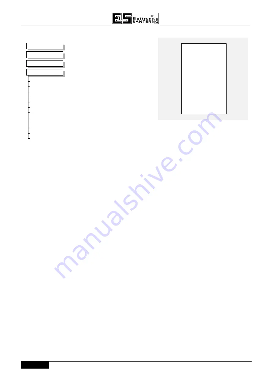
REFERENCE
REFERENCE
SPEED DEMAND [255] –– 0.00 %
SPEED SETPOINT [254] –– 0.00 %
REVERSE [256] –– FALSE
LOCAL SETPOINT [247] –– 0.00 %
LOCAL REVERSE [250] –– FALSE
COMMS SETPOINT [269] –– 0.00 %
0.00 % –– [245] REMOTE SETPOINT ––
0.00 % –– [248] SPEED TRIM
––
100.00 % –– [252] MAX SPEED CLAMP ––
-100.00 % –– [253] MIN SPEED CLAMP ––
FALSE –– [243] TRIM IN LOCAL
––
FALSE –– [249] REMOTE REVERSE ––
Parameter Descriptions
Parameter Descriptions
REMOTE SETPOINT
REMOTE SETPOINT
Range: -300.00 to 300.00 %
This is the target reference that the inverter will ramp to in remote reference mode (not
including trim), direction is taken from REMOTE REVERSE and the sign of REMOTE
SETPOINT.
SPEED TRIM
SPEED TRIM
Range: -300.00 to 300.00 %
The trim is added to the ramp output in remote mode (or if TRIM IN LOCAL is TRUE) to
form SPEED DEMAND . The trim is typically connected to the output of a PID in a
closed loop system.
MAX SPEED CLAMP
MAX SPEED CLAMP
Range: 0.00 to 100.00 %
Maximum value for SPEED DEMAND.
MIN SPEED CLAMP
MIN SPEED CLAMP
Range: -100.00 to 0.00 %
Minimum value for SPEED DEMAND.
TRIM IN LOCAL
TRIM IN LOCAL
Range: FALSE / TRUE
When TRUE, SPEED TRIM is always added to the ramp output. When FALSE, SPEED
TRIM is added only to Remote mode.
REMOTE REVERSE
REMOTE REVERSE
Range: FALSE / TRUE
Demanded direction when in Remote Reference mode. This is usually connected
directly to the Sequencing Logic.
SPEED DEMAND
SPEED DEMAND
Range: xxx.xh % (h)
Indicates actual speed demand. This is the input to the frequency controller.
SPEED SETPOINT
SPEED SETPOINT
Range: xxx.xh % (h)
Indicates target speed. This will be equal to either LOCAL SETPOINT, REMOTE
SETPOINT, JOG SETPOINT or COMMS SETPOINT. (Refer to the JOG function block
for the JOG SETPOINT parameter).
REVERSE
REVERSE
Range: FALSE / TRUE
Indicates demanded direction. This may not be the actual direction as no account of
setpoint sign is taken.
LOCAL SETPOINT
LOCAL SETPOINT
Range: 0.00 to 100.00 %
Indicates the Operator Station setpoint. It is always a positive quantity; saved on power
down. Direction is taken from LOCAL REVERSE.
Summary of Contents for SINUS/ISD 200 S-0.75
Page 56: ...15P0082B8 USER MANUAL SINUS ISD 5 14 14...
Page 144: ...15P0082A8 USER MANUAL SINUS ISD 8 2 2...
Page 166: ...15P0082B8 USER MANUAL SINUS ISD 10 16 16...
Page 180: ...15P0082B8 USER MANUAL SINUS ISD 12 8 8...
Page 184: ...15P0082A8 USER MANUAL SINUS ISD 14 2 2...
Page 186: ...15P0082B8 USER MANUAL SINUS ISD 15 2 12 MACRO1 MACRO1...
Page 188: ...15P0082B8 USER MANUAL SINUS ISD 15 4 12 MACRO2 MACRO2...
Page 190: ...15P0082B8 USER MANUAL SINUS ISD 15 6 12 MACRO3 MACRO3...
Page 192: ...15P0082B8 USER MANUAL SINUS ISD 15 8 12 MACRO4 MACRO4...
Page 194: ...15P0082B8 USER MANUAL SINUS ISD 15 10 12...
Page 195: ...SINUS ISD 15P0082B8 USER MANUAL 15 11 12...
Page 196: ...15P0082B8 USER MANUAL SINUS ISD 15 12 12...
Page 200: ...15P0082B8 USER MANUAL SINUS ISD 16 4 10...