Application manual
KNX room temperature controller EK-EQ2-TP
Release 3.00 - Updating: 27/06/2017
Application Manual
© SBS S.p.A. - All rights reserved
Page 44
Neutral zone and example of setpoint values correctly distributed
Until the actual (measured) temperature is located below the setpoint value for the heating, the operation is
heating; in the same way, if the actual value (measured) is greater than the setpoint value for the cooling, the
mode is cooling. If the actual value (measured) temperature is within the dead zone, the previous mode of
operation remains active; the switching point of the operation mode for heating / cooling must take place in
correspondence with the current setpoint for the active HVAC, in the same way the switching cooling /
heating must take place at the setpoint for heating.
Switch-over via KNX bus (mode 3)
The switch-over from the bus requires that the command is received from another KNX device, e.g. another
room temperature controller or a Touch&See unit configured to this purpose. The other device works in this
way as a “supervisor” device: the switch-over is triggered by the input communication object [DPT 1.100
heat/cool]. In this mode the manual switch-over by an enduser is disabled. Thanks to this mode, the
supervising device is able to control the “slave” devices with time-scheduled programs, extending their
functionality to that of a chronothermostat (centrally controlled by the supervising device).
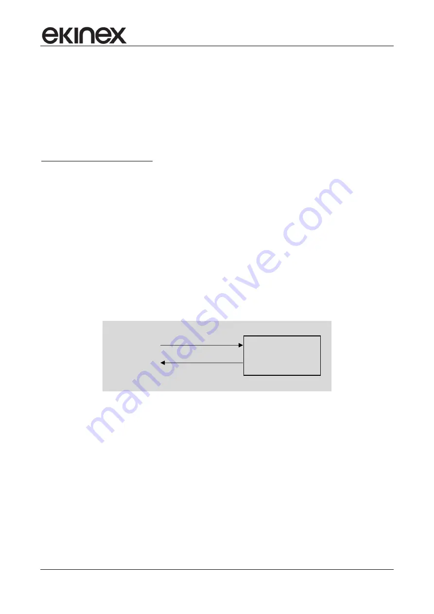
The communication objects indicated in the block diagram allows monitoring and modifying the current
conduction mode forced on the temperature controller. The object 48 –
Heating/cooling status out
is always
exposed, even when the thermostat function is set on heating or cooling only. When the function is set on
both heating and cooling, the cyclic sending on bus can be enabled; anyway, the information about the actual
conduction mode can be acquired with a reading request to this commiunication object.
The object 49 –
Heating/cooling status in
is exposed only when the function is both heating and cooling and
the switching among the different modes is performed by the bus.
7.8.1.3
Valve protection function
The function is suitable for heating and cooling systems that use water as thermal conveying fluid and are
provided with motorized valves for the interception of a zone or of a single room. Long periods of inactivity of
the system can lead to the blockage of valves: to prevent this, the room temperature controller may
periodically send a command to open / close the valve in the period of inactivity of the system. This
possibility is made available in the application program by means of the parameter "Valve protection
function", further defined by the frequency and duration of the valve control.
7.8.1.4
Remote Setpoint modification
The communication objects shown in figure allow to monitor the Setpoint forced modifications performed
locally by the user when interacting with the LCD display and the touch buttons of the room thermostat. The
49
– Heating/cooling status in
[1.100] heating/cooling
48
– Heating/cooling status out
[1.100] heating/cooling


