


10
P/N 120413
01/05
Installation
PresencePLUS
®
P4 EDGE
Banner Engineering Corp.
• Minneapolis, MN USA
www.bannerengineering.com • Tel: 763.544.3164
Hardware Installation Overview
Following is an overview of the procedure for connecting and powering up the basic hardware. Details are provided in the
subsections that follow.
1. Read
2. Check for the following essential components:
-
Lens
-
Sensor and cable
-
Communication cable (Ethernet or serial)
-
486 microprocessor or faster personal computer running Microsoft Windows ME, NT, 2000, or XP operating system
-
Power supply with 10–30V dc and 500 mA maximum current
-
Light source. Every application requires a light source; however the Sensor can be used without a dedicated light source.
-
Trigger source (example: Banner WORLD-BEAM
®
QS18VN6D sensor)
3. Thread the lens onto the Sensor’s lens mount.
4. Connect the communication cable between the PC and Sensor.
5. Connect the trigger source (see step 2 above) to the Sensor as follows:
a) Connect brown wire to +V dc.
b) Connect blue wire to –V dc.
c) Connect black wire to pink wire from Sensor cable.
6. Connect the power supply to the Sensor as follows:
a) CV to brown wire of cable.
b) Connect –V to blue wire of cable.
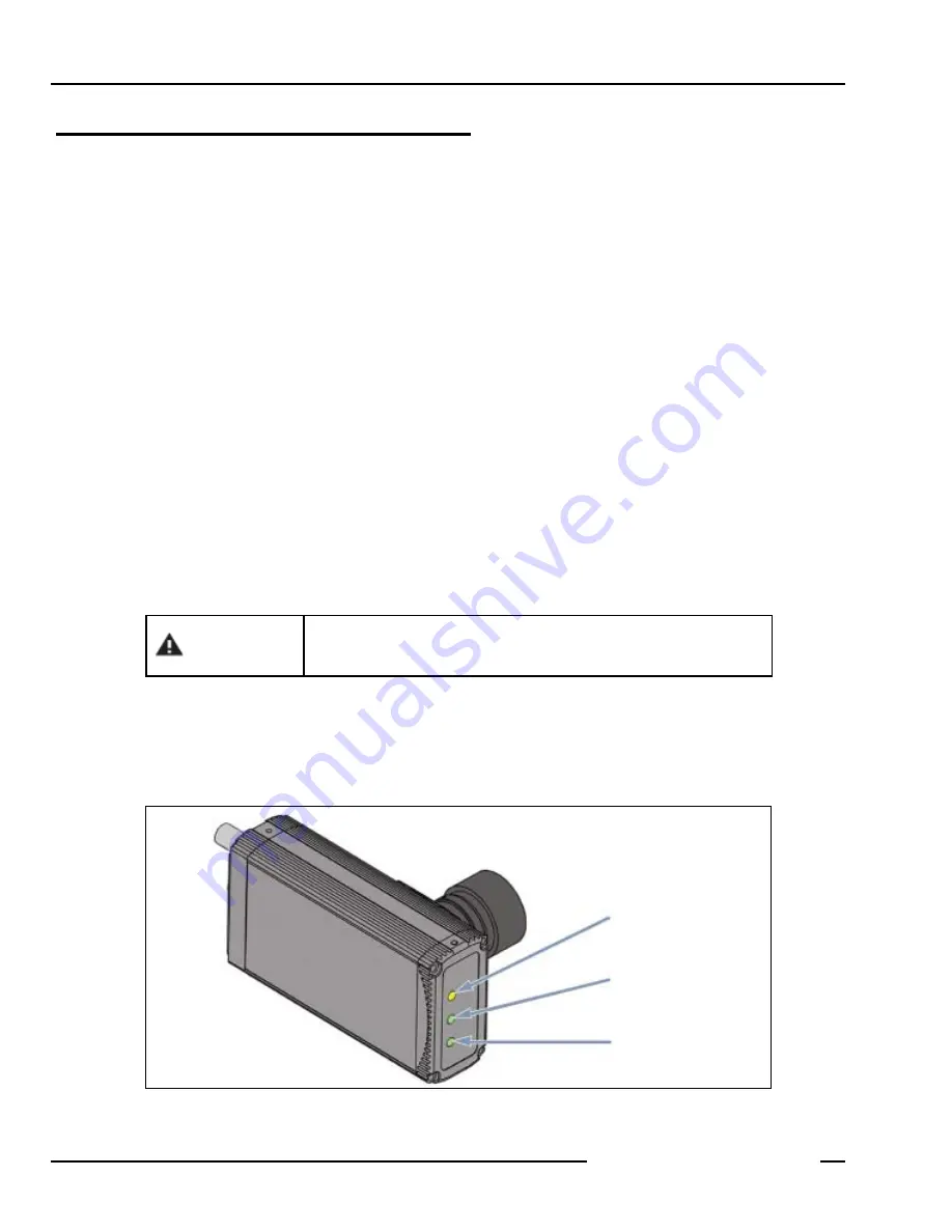
7. Power up the hardware and verify that the Red Error LED turns OFF. During power-up, all the Sensor LEDs turn ON for 15
to 20 seconds (see below).
8. Install PresencePLUS P4 software on the host PC (see
9. Start the PresencePLUS P4 program and verify system connections (see
PresencePLUS P4 LEDs
The Sensor alone will operate properly with input voltage of 10–30V dc; however,
if a light source is powered by the Sensor, input voltage must be 24V dc ± 10%.
CAUTION
Green = Pass
Red = Fail
Green = Ready
Yellow = Trigger
Green = Power
Red = Error
Summary of Contents for PresencePlus P4
Page 1: ...Printed in USA P N 120413...
Page 3: ...This User s Manual reflects Sensor Firmware Version 1 0 0 and GUI Software Version 2 0 2...
Page 4: ......
Page 8: ......
Page 180: ......
Page 181: ......


