Installation and Setup
71
1. The laptop is booted and ready
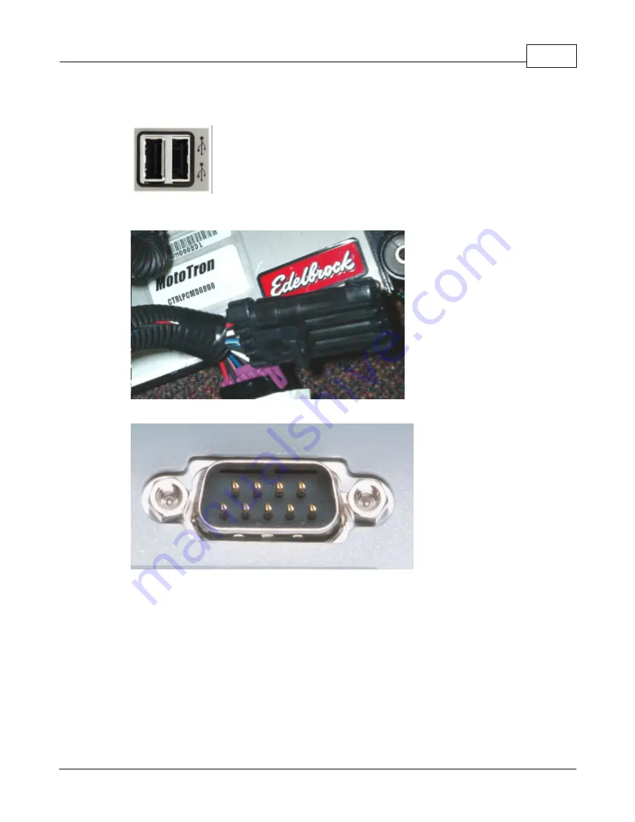
2. The USB Key is plugged into an available USB slot on the computer
3. The Computer Connection cable is plugged into the Interface connector on the
harness
4. The Computer Connection cable is plugged into the PC's serial port
5. The ignition key is in the
ON
position
Once everything is hooked up to the PC and the harness, look for an LED light (steady)
on the gray colored interface module (part of the Computer Connection cable). This
indicates a powered connection and the PC is ready to communicate. As the computer
communicates to the vehicle ECU, a few cables may have additional
red
and
green
LEDs
that will blink. This indicates data is flowing back and forth between the PC and the ECU.
Note: Avoid repeated unplugging or disconnect of the USB adapter or
serial cable. Microsoft windows will occasionally not reconnect properly. If
you have trouble reconnecting after plugging in hardware, or after
hibernation. Rebooting the machine will usually clear it up.
Summary of Contents for Pro-Tuner
Page 27: ...Installation and Setup 27 Figure 6 Solder or weld the return hard line to the fuel pickup line...
Page 49: ...Installation and Setup 49 with a recommended sensor inlet tube installed...
Page 69: ...Installation and Setup 69...
Page 79: ...Installation and Setup 79 15 Click OK to complete the set up...
Page 82: ...82 Click NEXT Click NEXT...
Page 86: ...86...
Page 103: ...Basic Tuning with the Pro Tuner System 103 manipulation...
Page 108: ...108 4 3 Tuning Maps Visit us at http www edelbrock com Tuning Maps...
Page 122: ...122...
Page 125: ...Basic Tuning with the Pro Tuner System 125 Tuning Tips...
Page 127: ...Basic Tuning with the Pro Tuner System 127 0 712 1 405 20 66...
Page 143: ...Basic Tuning with the Pro Tuner System 143...
Page 166: ...166...
Page 170: ...170...
Page 233: ...Appendices 233...
Page 234: ...234...
Page 235: ......


