


36
Eaton
®
Power Xpert
®
9395P-600 (300V-600V) Installation and Operation Manual 164000710—Rev 07
33..22..66
U
UP
PS
S S
Syysstteem
m P
Poow
weerr W
Wiirriinngg P
Prreeppaarraattiioonn
Read and understand the following notes while planning and performing the installation:
•
Refer to national and local electrical codes for acceptable external wiring practices.
•
To allow for future kVA upgrades, consider installing a derated UPS using wiring and external overcurrent
protection breakers sized for a fully rated UPS.
•
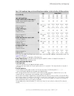
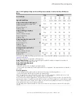
For external wiring, use 75 °C copper or aluminum wire. Wire sizes listed in
through
are
for copper wiring only. If wire is run in an ambient temperature greater than 30 °C, higher temperature wire
and/or larger size wire may be necessary. Wire sizes are based on using the specified breakers.
•
Wire ampacities are chosen from Table 310-16 of the National Electrical Code
®
(NEC
®
). Specification is for
copper wire with a 75º C rating.
•
Material and labor for external wiring requirements are to be provided by designated personnel.
•
If installing a maintenance bypass, a minimum of two separate feeds with upstream feeder breakers, or a
single feed with two upstream feeder breakers, must be provided: one for the UPS or rectifier input
breaker (RIB) (if installed) and one for the maintenance bypass input. DO NOT use a single feed or a single
feeder breaker to supply both the UPS or RIB and the maintenance bypass. If a bypass input breaker (BIB)
is installed in the maintenance bypass and a single-feed UPS is being installed, a single feed to the
maintenance bypass is acceptable for supplying both the UPS and the bypass.
•
The bypass and rectifier feeds into this equipment use three wires. The phases must be symmetrical
about ground (from a Wye source) for proper equipment operation.
•
The Eaton 9395P-600 600V and 480V unit is designed for operation on a grounded-wye source of supply.
There is no additional connection point for a neutral conductor. The output of this UPS will not directly
support phase to neutral loads.
•
The ISBM and UPM sections are shipped with debris shields covering the ventilation grills on top of the
sections. Do not remove the debris shields until installation is complete. However, remove the shields
before operating the UPS. Once the debris shields are removed, do not place objects on the ventilation
grills.
•
In a common battery system, all UPMs are powered from one common battery source. In a separate
battery system, each UPM is powered from separate battery sources.
•
UPSs in distributed bypass and parallel systems must use a separate battery system for each UPS.
•
On a UPS configured as an Input Output Module (IOM), requirements for bypass input wiring, termination,
conduit, and bypass breaker are not applicable.
If the power rating listed on the nameplate of the installed UPS is not found in the following tables, wire the
UPS using the fully rated specifications. Otherwise, calculate the required wire, conduit, and breaker sizes
using the following guidelines in addition to those already listed in paragraph
UPS System Power Wiring Preparation
•
Select wire size according to the UPS nameplate.
•
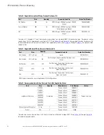
Do not use wire larger than the largest size listed in
through
.
•
Use terminal recommendations from
through
•
Size and number of conduits must not exceed those listed in
through
.
•
Select overcurrent protection input, battery, and output breakers according to the UPS nameplate rated for
either 80% or 100%.
•
Follow all applicable NEC and local codes.
Wire sizes listed are for copper wiring only.
Summary of Contents for Power Xpert 9395P-600/600
Page 8: ......
Page 226: ...16400071007 164000710 07...