


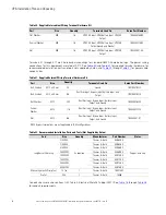


60
Eaton
®
Power Xpert
®
9395P-600 (300V-600V) Installation and Operation Manual 164000710—Rev 07
Read and understand the following notes while planning and performing the installation:
•
Use Class 1 wiring methods (as defined by the NEC) for interface wiring from 30V to 600V. The wire
should be rated at 600V, 1A minimum and 12 AWG maximum.
•
Use Class 2 wiring methods (as defined by the NEC) for interface wiring up to 30V. The wire should be
rated at 24V, 1A minimum. When Class 2 circuit wiring must be mixed with Class 1 wiring, use Class 1
wire and wiring methods.
•
Use shielded twisted-pair wires for each input and return or common.
•
All interface wiring and conduit is to be provided by the customer.
•
When installing external interface wiring (for example, building alarm, relay output, battery breaker trip, and
X-Slot) to the UPS interface terminals, conduit must be installed between each device and the UPS
cabinet.
•
Install the interface wiring in separate conduit from the power wiring.
•
When installing internal interface wiring to X-Slot terminals, route the wiring through the internal opening in
the X-Slot communication bay.
•
All building alarm inputs or remote features require an isolated normally-open contact or switch (rated at 24
Vdc, 20 mA minimum) connected between the alarm input and common terminal. All control wiring and
relay and switch contacts are customer-supplied and may need to use Class 1 wiring, see above.
•
The building alarms can be programmed to display the alarm functional name.
•
LAN drops for use with X-Slot connectivity cards must be provided by the customer and may need to use
Class 1 wiring, see above.
•
The UPS battery aux signal wiring from the UPS must be connected to the battery disconnect device.
•
A supplemental 48 Vdc shunt trip signal for the battery disconnect device is provided, but is not required
for normal operation.
•
Battery aux and 48 Vdc shunt trip wiring should be a minimum of 18 AWG.
•
The REPO feature opens all contactors in the UPS cabinet and isolates power from your critical load. Local
electrical codes may also require tripping upstream protective devices to the UPS.
•
The REPO switch must be a latching-type switch not tied to any other circuits.
•
A jumper wire must be connected between pins 1 and 2 on TB1, if the normally-closed REPO contact is
not used.
•
REPO wiring should be a minimum of 22 AWG and a maximum of 14 AWG.
•
The REPO switch wiring must be in accordance with NEC Article 725 Class 2 requirements.
•
The maximum distance between the REPO and the UPS cannot exceed 150 meters (500 feet).
•
Alarm relay contacts have a maximum current rating of 5A and a switched voltage rating of 30 Vac and 28
Vdc.
•
Alarm relay wiring should be a minimum of 22 AWG.
Summary of Contents for Power Xpert 9395P-600/600
Page 8: ......
Page 226: ...16400071007 164000710 07...