


Eaton
®
Power Xpert
®
9395P-600 (300V-600V) Installation and Operation Manual 164000710—Rev 07
97
Figure 43. REPO Switch
Contact Block (Back View, Faceplate Removed)
REPO Switch (Front View)
5.
To gain access to terminal block TB1 and the interface entry conduit landing plate, remove the screws
securing the top internal safety shield panel and remove the panel. Retain the hardware for later use (see
).
6.
Remove the left interface entry conduit landing plate to drill or punch holes (see
).
7.
Reinstall the interface entry plate and install conduit.
8.
To locate the appropriate terminals and review the wiring and termination requirements, see paragraph
UPS System Power Wiring Preparation
, and
.
9.
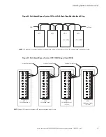
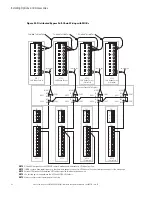
Route and connect the wiring as shown in
and
10. If the normally-closed REPO TB1 connection in the UPS is not used, connect a jumper wire between pins 1
and 2 on TB1.
11. If you are installing multiple REPO switches, wire additional switches in parallel with the first REPO.
Table 34. REPO Wire Terminations
From REPO Station(s) Switch
Contact Block (Either Block)
To Customer Interface
Terminal Board TB1 in UPS
Cabinet
Wire Size
Tightening Torque
3 NO
TB1 3
Twisted Wires (2)
14 22 AWG (0.75
4.0 mm2)
7 lb in (0.8 Nm)
4 NO
TB1 4
Summary of Contents for Power Xpert 9395P-600/600
Page 8: ......
Page 226: ...16400071007 164000710 07...