


U n i v e r s a l l y
A d j u s t a b l e V D T
S t a n d
Tools Required
- 4mm Allen wrench (provided)
-5mm Allen wrench (provided)
-6mm Allen Wrench (provided)
-Phillips head screwdriver
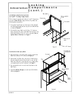
1. Attach the
Feet
to the adjustable
Base Frame
using
the M8 x 1.00”(25mm) Socket head screws and lock
washers. Tighten securely using the 6mm wrench.
Install the round
and square
End Caps
on the
Feet. See
Figure 1
.
NOTE
: Install the Feet with the longer portion to
the rear of the unit.
2. Assemble the left and right hand
Top Supports
to
the Base Frame using the M8 x .64”(16mm) Socket
flat head cap screws. Tighten securely using the
5mm wrench. See
Figure 1
.
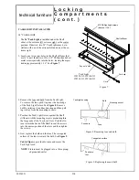
3. Place the
Rear Surface
(keyboard and monitor lam-
inate tops are packaged separately) onto the rear
Top Supports. Align the holes in one of the
Surface
Mount
with the holes in the bottom of the Rear Sur-
face. Note that the Top Supports are sandwiched be-
tween the Rear Surface and the Surface Mounts.
Attach the Surface Mounts to the Rear Surface using
the #8 x 1.25”(30mm) screws provided. Repeat this
procedure for the
Front Surface
. See
Figure 2
.
NOTE
: The radiused side of both Surfaces face to-
wards the front of the unit.
4. The
Front Crank Assembly
may be installed on the
left or right side of the unit. Fasten the
Mounting
Block
to the appropriate Top Support using the two
M-5 x .38”(10mm) Socket head screws provided.
Tighten securely using the 4mm wrench. See
Figure
2
.
Insert the Front Crank Assembly through the Mount-
ing Block and onto the
Drive Pin
located on the
Base Frame. Fasten the Crank Assembly to the Drive
Pin with the
Connector Clip
. See
Figure 2
.
5. Install the removable
Rear Crank
into the Rear Sur-
face drive mechanism on either side of the Surface.
The holes in the Surface must be aligned with the
drive mechanism on the Base Frame. See
Figure 2
.
Universally Adjustable VDT Stand
Figure 1
Foot
Square end
cap
Round end
cap
Adjustable base
frame
M-8 x 1.00”(25mm)
Socket head cap
screws
Washers
M-8 x .64”(16mm)
Socket flat head
screws
Top support
Rear crank
Front surface
Rear surface
Surface mount
Front crank
assembly
Mounting block
M-5 x .38 (10mm)
Socket head screws
Connector
clip
#8 x 1.25” (30mm)
screws
Figure 2
82743
technical furniture
B-1
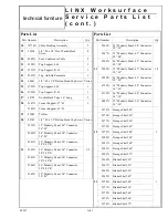
Summary of Contents for LINX
Page 1: ...Modular Furniture LINX Modular Furniture Installation manual...
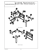
Page 24: ...84913 Bolt on Peninsula P e n i n s u l a B o l t o n technical furniture...
Page 41: ...R e t r o f i t K i t N o v a c o n t 86270 technical furniture A 34...
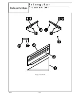
Page 51: ...84571 Triangular Connector T r i a n g u l a r C o n n e c t o r technical furniture A 44...
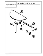
Page 53: ...84252 85217 Conference End C o n f e r e n c e E n d technical furniture A 46...
Page 56: ...81071 B C o n f e r e n c e T a b l e technical furniture A 49...
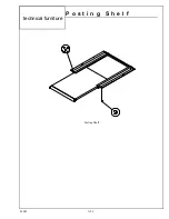
Page 57: ...84085 Posting Shelf P o s t i n g S h e l f technical furniture A 50...
Page 58: ...81046 Storage Shelf S t o r a g e S h e l f technical furniture A 51...
Page 78: ...80954LX L o c k i n g C o m p a r t m e n t s c o n t technical furniture D 11...
Page 112: ...85089 W h i t e P e g A n d B i n B o a r d s c o n t technical furniture E 12...
Page 119: ...85082 F a b r i c T e c h W a l l c o n t technical furniture E 19...
Page 122: ...85093 C o r n e r L a m i n a t e H o o k O n S h e l v e s c o n t technical furniture E 22...


