background image

3-10

Control panel

Access levels

The menu system gives the operator access to menu items that are relevant according to access level.

The access levels shown below are also illustrated in the "Menu diagram" on the facing page.

Access level

Menu diagram color

'Operator' level

Black

No access code needed

'Trained Operator'
level

Blue

Code needed.

Change of access levels

NOTE:

The default access level is Operator.

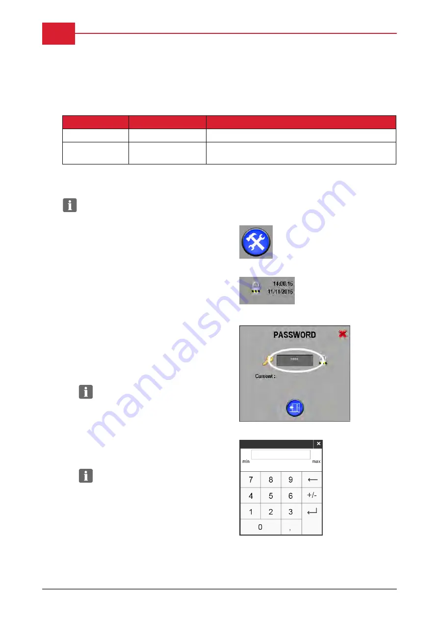
1.

Press the 'Setup' button.

2.

Press the padlock symbol in the upper right
corner of the control panel.

The change access dialog opens.

Change of access level requires a 4-digit
numeric code for:

Trained Operator

The access code is supplied with the
equipment on delivery after training.

NOTE:

Contact local DuPont Service

if the code for Trained Operator is lost.

3.

Press the 'key' area to enter the access code.

A numeric keypad will be displayed.

4.

Enter the 4 digit access code.

NOTE:

Entering an incorrect code with

automatically reset access level to
Operator level (= locked).

Operation Manual

|

Cyrel FAST 2000TD

January, 2020

Summary of Contents for Cyrel FAST 2000TD

Page 1: ...T 2000TD IMPORTANT Please keep this manual with other equipment documentation for future reference Please keep this manual with the 2000TD for future reference January 8th 2020 Edition BD10082030 Engl...

Page 2: ...s valid for equipment with serial no s starting from Cyrel FAST 2000TD 8106 The Cyrel FAST 2000TD is manufactured by Glunz Jensen A S Lindholm Havnevej 29 DK 5800 Nyborg Denmark This manual is publish...

Page 3: ...and or act according to the information in order to obtain the best possible function of the equipment CAUTION The operator must observe and or act according to the information in order to avoid any...

Page 4: ...ensen does not take any responsibility for any damage or accidents caused by unintended use of the equipment It is absolutely prohibited to make any modifications electrical or mechanical of the equip...

Page 5: ...nd other electronics parts must be sent to a suitable waste deposit Service assistance If help is needed to correct any problem with the equipment please contact your local supplier January 2020 Opera...

Page 6: ...0 9 Warning labels yellow labels 0 9 Instruction labels blue labels 0 9 Emergency stops 0 10 Functional description 1 1 Processing description 1 2 Feed and exit 1 6 Clamp bars and transport arms 1 7...

Page 7: ...rs 3 2 Buttons and fields 3 3 Alarms 3 7 Alarm history 3 9 Access levels 3 10 Change of access levels 3 10 Menu diagram 3 11 Tools menus 3 12 User settings 3 15 Statistics 3 16 Maintenance 3 17 Moving...

Page 8: ...0 8 Table of Contents Replacing the slip fit adapter B 1 Air filter B 8 Operation and filling of the SMC chiller B 11 Operation Manual Cyrel FAST 2000TD January 2020...

Page 9: ...the Safety Instruction Manual please also observe and act according to the warning labels mounted on the equipment itself Label Description Label Description High Voltage Risk of hand injury gear dri...

Page 10: ...ne located on each of the right and left top side panels Pushing an emergency stop will instantly Make the processor stop Switch off the heating Stop the drum movement Pull back the heated roller Show...

Page 11: ...5 Nip Nip comprised of two rollers the format cylinder and the heated roller The nip pushes a nonwoven and PET material onto the plate surface By very high temperature the nonwoven material absorbs th...

Page 12: ...s positioned and runs correctly If for any reason the plate is not positioned attached correctly it is possible to stop the process exit the plate and reposition and restart the process For detailed i...

Page 13: ...static drum The rear edge of the plate enters the processor The rear edge of the plate stops over the rear clamp bar The stamper bar will press the rear edge of the plate into the rear clamp arm pin...

Page 14: ...c drum for the number of revolutions defined for the selected program Close to the nip the polymer plate is preheated by means of an IR heater and when it reaches the nip heated by the heated roller O...

Page 15: ...tox to be catalyzed and then removed from the processor via an external exhaust system Once the full number of revolutions has been completed the processor will automatically position the front clamp...

Page 16: ...aching it The plate will now be completely released from the clamp bar and can be removed from the exit slot Once the plate has been fully ejected from the processor both clamp arms will automatically...

Page 17: ...l which then sends an alarm to the operator Likewise when the waste roller is full Nip The nip A comprises two rollers the format cylinder FC and the heated roller HR The heated roller moves down to c...

Page 18: ...to the exhaust duct Control panel The control panel holds all the processor operating and control functions The control panel is a finger touch panel with a graphic illustration of the processor itsel...

Page 19: ...ician Make sure that the chiller unit is switched ON Procedure 1 Locate the main power switch in the front left side panel and switch power to ON The control panel will start up displaying Machine ill...

Page 20: ...catox system to reach the set temperature 7 During initialization the display presents buttons and processor overview as described in the following The Stop button will be presented and the top line w...

Page 21: ...ions will be displayed in yellow while heating up The blue ON OFF will stop flashing when correct temperature is reached The heated roller and catox area will both be green Start up is then complete a...

Page 22: ...ess the Home button to return to home view 4 While cooling down a cooling down message will be displayed NOTE It will take approx 40 min for the heated roller and the catox system to cool down CAUTION...

Page 23: ...W PET and Waste on page 3 2 Plate Preparation Ensure the plate is in a good condition and ready for processing CAUTION The plate should have straight square cut edges without damage and the plate surf...

Page 24: ...mm 17 7 63 3 Gently push the plate into the entrance slot so that the front edge of the plate rests on the 2 front stops If positioned correctly the stack light will change from green to blue Release...

Page 25: ...label on the plate package lists all the information needed for the job selection First Cycle 1 A processing job consists of several processing cycles Normally all processing jobs will start from cyc...

Page 26: ...e 3 12 Plate gauge 3 Enter the thickness gauge of the plate Plate gauge is shown in imperial units thousands of an inch A drop down menu will display the available plate gauges Available plate gauges...

Page 27: ...d plate program based on the data set in the fields 1 to 5 or the text NoValidJobSetup which indicates that settings in either the Plate gauge or Plate type field do not match any of the pre programme...

Page 28: ...l ejection could be emergency stop has been activated top front or rear covers have been opened during processing or an alarm which requires ejection removal of the plate If for some reason you need t...

Page 29: ...es from yellow to blue 2 Press the Eject button to release the plate from the rear clamp arm The stack light turns back to yellow 3 At the same time grab the plate to avoid it dropping on the floor Wh...

Page 30: ...w display the blue Eject button Press the Eject button once this will eject the rear edge of the plate and hold onto the plate as the next operation will release the plate completely from the processo...

Page 31: ...fter loading this can be done at any point through the program until the automatic ejection procedure starts The reason for manual ejection could be Incorrect plate parameters have been entered into J...

Page 32: ...sing only the rear arm Plate attached to FRONT arms Selective ejection using only the front arm Forward and Rearward Using these buttons move the clamp arms together to allow observations to the curre...

Page 33: ...the Ready to initialize view and then shortly after change to the Eject plate view Press the Eject button to eject the plate from the processor The control panel will display the Ejecting plate messag...

Page 34: ...ay attention to the clamp arm position when removing covers Machine S N 8056 onwards and retrofitted machines the clamp arm motors are fitted with brakes so the clamp arms will not move when the power...

Page 35: ...on Manual part No 21741 whereas specific instructions for the Translyft lift table are described in this manual In case of using a lift table from another supplier please refer to the other supplier s...

Page 36: ...l support CAUTION Raise the roll support before placing a roll in the roll positioning guide The roll positioning guide has two markers a for positioning of a 37 wide roll b for positioning of a 44 wi...

Page 37: ...Operation procedures 2 19 Blank January 2020 Operation Manual Cyrel FAST 2000TD...

Page 38: ...3 0 Panel overview Panel overview Operation Manual Cyrel FAST 2000TD January 2020...

Page 39: ...is manual Ref Area name Description Access level A Processor state Overall processor status messages e g warming up running cover open etc Visible in all control panel views and sub menus In case of a...

Page 40: ...ssing still possible Change roll after processing If the alarm is raised during processing the alarm will appear as a yellow alarm in the alarm history log Red Roll diameter is critical The process cy...

Page 41: ...views except the Home view switches view to the home view from any sub view when pressed and at the same time the Home button will be replaced by the ON OFF button described above HOME button Heating...

Page 42: ...rgency stops Return button Accessible from all views Exception Inaccessible from home view For each activation the view will return to previous screen For quick return to the home view press the Home...

Page 43: ...ed processor state must be Ready pressing Start will start the processing cycle Pressing Stop will display the abort dialog Pressing Stop before the end of a processing cycle will prompt the operator...

Page 44: ...elds are inaccessible when white with grey text numbers Keypad Accessible only when pressing an input field which requires a keypad Keypad is presented either as alphanumerical or numerical depending...

Page 45: ...n Action Status color Stack light Stack light behaviour Blue steady Ready for plate loading Green steady Plate loaded correctly or process finished Operator action needed Blue steady Process is runnin...

Page 46: ...f the alarm has been removed Initialization is needed after confirmation of alarm Red steady Alarms view By pressing the Alarm button in any view a complete list of the present alarms will be displaye...

Page 47: ...ystem messages stored in the PLC Buttons Use the buttons in the right side of the display to navigate between the alarms Scroll up down one line Scroll up down one page Colors codes White Message or a...

Page 48: ...ress the Setup button 2 Press the padlock symbol in the upper right corner of the control panel The change access dialog opens Change of access level requires a 4 digit numeric code for Trained Operat...

Page 49: ...Control panel 3 11 Menu diagram January 2020 Operation Manual Cyrel FAST 2000TD...

Page 50: ...gs and service menus General settings User settings Statistics Maintenance Diagnostics Change of access level General settings General settings cover basic settings for screen text parameter values da...

Page 51: ...e number and choice of available languages may depend on the version of software installed Selection will be effected immediately No need for restart Regional settings Select between metric imperial a...

Page 52: ...reflected in time stamps for the alarm history log files etc Serial Number Displays the serial number of the processor NOTE Please inform the serial number when calling for service The serial number...

Page 53: ...only by authorized personnel 3 There are 2 options for inputting the Nonwoven width Select the Nonwoven width by using one of the 2 quick set buttons or press the Nonwoven width field to open the num...

Page 54: ...rs Statistics in total and Statistics since last maintenance The same view is accessible through the General settings button CAUTION Resetting of statistics is done by authorized personnel only Press...

Page 55: ...played When the message changes to STATE STOPPED the green LED is lit and the Arms to Service pos button can be activated Moving arms manually Move the arms and at the same time visually check the pos...

Page 56: ...Diagnostics allows access to the Diagnostics Menu The Diagnostics menu gives access to Manual functions for web feed and stack light test Operation check of sensors and guard switches Operation Manual...

Page 57: ...web The LED is lit when the Man WEB feed button is pushed The button has same function as the blue button placed at the right side panel when standing at the rear side of the processor Diagnostics sh...

Page 58: ...diagnostics The machine diagnostics screen shows actual position and status of the sensors in a graphical presentation of the processor NOTE LEDs are green when sensors are active Operation Manual Cyr...

Page 59: ...xhaust system Call a service technician if noise smell or leakage appears to come from the processor or the chiller unit Heat and ventilation Make sure that room temperature is between 18 C 64 4 F and...

Page 60: ...rgency stops on page 0 10 If any operations fail call a service technician WARNING Do not use the processor unless ALL the safety devices are fully operational Cleaning the air filter The moisture and...

Page 61: ...commended It should be inspected and cleaned on an everyday basis as residuals from the processing will stick to the rollers and reduce the processing quality if not removed regularly Tools required A...

Page 62: ...or level password This will be provided during training and will only be available to operators who have been correctly instructed in the correct cleaning procedure and appropriate safety precautions...

Page 63: ...l automatically rotate both sets of clamp arms to the low position in the machine Once in position the lamp will turn green 13 Once the arms are in the safe position the black plastic stripping finger...

Page 64: ...id and clean the rubber roller Keep doing this process until the rubber roller is clean 18 Once the cleaning is finished return to the main operation Home screen If any alarms are generated go to the...

Page 65: ...ess of how full it is and an empty core fitted see section about changing the waste roll Tools required Translyft or other lifting device Please see detailed description of operating the Translyft lif...

Page 66: ...l above with duct tape as shown 2 5 Manually turn the chuck bearing of the roll until the lock is in the 12 o clock position The photo is for illustrative purpose only 6 Unlock the chuck bearing in th...

Page 67: ...e lift table underneath a roll in the processor 9 Place the lift table underneath the roll until the roll is right above the positioning guide on the lift table 10 Use the handle on the lift table to...

Page 68: ...Place the new roll in the positioning guide on the Translyftlift table CAUTION For correct mounting and threading of the material in the processor it is important that the coil direction of the roll i...

Page 69: ...ehind the processor 20 Adjust the height of the lift table to enable mounting the roll air shaft into the chuck bearings CAUTION Be very careful not to damage any parts inside the processor when pushi...

Page 70: ...haft s connection block is correctly positioned in the chuck bearing holder 23 Slowly lower the lift table until the air shaft is resting in the chuck bearings 24 Pull away the lift table Operation Ma...

Page 71: ...tape down the entire length of the new roll 1 NOTE The heat resistant tape Tesa 4965 50 mm 2 is recommended 27 Remove the protection paper from the double side tape 28 Detach the end of the old mater...

Page 72: ...n button CAUTION Do not release the button untill the material has been fully wound into the processor and the join is on the waste roll by at least 2 revolutions 31 Close the rear cover 32 Press the...

Page 73: ...fting device Please see detailed description of operating the Translyft lift table on page 2 17 NOTE The lifting device is an optional extra Pair of scissors or stanley knife Double side self adhesive...

Page 74: ...s of nonwoven and PET to the top cover Each layer separately nonwoven first and PET on top of the nonwoven 6 Manually turn the chuck bearing of the roll until the lock is in the 12 o clock position Th...

Page 75: ...il the roll is right above the positioning guide on the lift table CAUTION Be very careful not to damage any parts inside the processor when lifting the roll 11 Use the handle on the lift table to rai...

Page 76: ...clip Position a 37 roll to align with the groove The roll is positioned correctly when the roll end aligns precisely with the groove in the air shaft 19 Mount the air shaft with the empty roll in the...

Page 77: ...block is correctly positioned in the chuck bearing holder 21 Lock the chuck bearings in left and right side by pressing the chuck bearings inwards towards the roll The photo is for illustrative purpos...

Page 78: ...tape Tesa 4965 50 mm 2 is recommended 23 Loosen the PET from the top cover and mount it to the empty roll 24 Mount another piece of double side self adhesive tape on top of the PET for mounting of the...

Page 79: ...N Do not release the button until the material has been fully wound into the processor and the join is on the waste roll by at least 5 revolutions and the NW and PET web is tight 28 Close the rear cov...

Page 80: ...e side self adhesive heat resistant tape e g Tesa 4965 50mm 2 heat resistant up to 200 C transient 100 C prolonged Strong duct tape 50 mm wide Procedure 1 Press the ON OFF if light blue indicating tha...

Page 81: ...e the air hoses 7 This overview shows correct threading of the nonwoven PET and waste Follow the steps below when threading 8 Lead the PET foil below the roller A and back above the PET roll and out o...

Page 82: ...ples CAUTION Do not use staples 12 Lead the tip of the nonwoven PET back inside the processor and underneath the anti static brush B and above the roller C 13 Lead the tip of the nonwoven PET in betwe...

Page 83: ...g piece of the double sided self adhesive tape down the entire length of the empty cardboard roll NOTE The heat resistant tape Tesa 4965 50 mm 2 is recommended 18 Loosen the PET from the top cover and...

Page 84: ...e to the air coupling 22 Press the blue web rotation button CAUTION Do not release the button until the material has been fully wound into the processor and the join is on the waste roll by at least 5...

Page 85: ...ress the ON OFF button 26 Then press the Heating Power ON button to switch the heating on 27 Initialise the machine When the processor is heated up it s ready for processing January 2020 Operation Man...

Page 86: ...Operation Manual Cyrel FAST 2000TD January 2020...

Page 87: ...an 001 014 Safety override switch activated The processor cannot be started Please call an authorized Service Technician 001 015 Manual logging activated The processor cannot be started Please call an...

Page 88: ...031 002 032 002 033 002 034 Rear Clamp Arm drive error Motor could not move as expected Check for jammed plates and mechanical failures before initializing If the problem persists please call an auth...

Page 89: ...gage functional safety error Please call an authorized Service Technician 005 003 Nip engage torque is not reached within specified process distance NIP engage system HR torque could not be reached pl...

Page 90: ...o fast Web PET rotation too fast please check for empty supply rolls broken web materials and if machine is threaded correctly 007 008 Web waste roll is full Web Waste roll is full please change 007 0...

Page 91: ...wn remove broken web and re thread 007 032 WEB NW drive error 39022 Battery low warning Please call an authorized Service Technician 007 033 WEB PET drive error 39022 Battery low warning Please call a...

Page 92: ...heat exchanger HX If alarm can t be reset please call an authorized Service Technician 009 013 Catox Temperature at T4 too low Please check catox or call service If alarm can t be reset please call a...

Page 93: ...Delivered with the equipment Dismounting the old slip fit adapter 1 Set access level to Trained operator on the control panel See description of Change of access levels on page 3 10 2 Select Tools Ma...

Page 94: ...e single threaded hole 2 When tightened it will lift the bushing and release it from the shaft 9 Remove the set screw from the taper lock 10 Mount the lift shaft delivered with the equipment and dismo...

Page 95: ...fixation ring NOTE Before mounting the slip fit adapter notice the pin on the format cylinder This pin fits into a slot in the slip fit adapter 13 Mount the air hoses included with the tool kit in two...

Page 96: ...isengage from the retaining pin placed in the other end of the format cylinder Rotation can be either clockwise or anti clockwise Rotate until the pin is in the centre of the slot and when you feel it...

Page 97: ...fit adapter notice the pin on the format cylinder This pin fits into a slot in the slip fit adapter 21 Mount the air hoses included with the tool kit in the two fittings in the end of the format cylin...

Page 98: ...at the time of delivery 24 Rotate the slip fit adapter in the clockwise direction a few degrees until the slip fit adapter rotation stops This indicates that the pin is fully engaged in the slot 25 T...

Page 99: ...31 Dismount the lift shaft 32 Mount both of the set screws Use the allen key No 6 33 Tighten both set screws evenly with a torque wrench to 35 Nm to a maximum of 49 Nm 34 Mount the left side panel 35...

Page 100: ...be in the anti clockwise position for auto venting In the clockwise position the drain valve will be closed all the time Cleaning the air filter WARNING This operation has to be carried out with the s...

Page 101: ...Alternatively shut off the compressed air supply to the processor 2 Open the right side cover and locate the air filter unit photo 3 Dismount the moisture trap housing by turning the housing to the le...

Page 102: ...tom part of the filter see photo and clean in water 6 Re assemble the filter 7 Mount the moisture trap housing by pushing upwards into the filter assembly and turn to the right to lock Operation Manua...

Page 103: ...is switched to ON 2 To Start Keep the RUN STOP key pressed for approx 2 seconds The RUN lamp lights up in green and the chiller will start to run 3 To fill the chiller remove the Tank Lid and carefull...

Page 104: ...ty of the chiller is 5 Litres the capacity of hoses and heat exchangers Therefore please have available 5 Litres of anti freeze which when diluted to 15 20 will provide up to 30 Litres of ready mixed...

Page 105: ...OP key pressed for approx 2 seconds The RUN lamp flashes green and continues the operation until the chiller is ready to stop After approx 15 seconds the RUN lamp goes off and the chiller stops Januar...

Page 106: ...B 14 Appendix B Blank Operation Manual Cyrel FAST 2000TD January 2020...

Reviews: