


Chapter 3 – Installation and Wiring
3–12
GLC2400/2500/2600 Series User Manual
Failsafe Electrical Circuits
When designing failsafe circuits, be aware of possible malfunctions resulting from
differences in the startup times of the control device connected to GLC output unit
(especially the DC power supply), the GLC unit’s system, and the program. When
using a remote I/O, create a logic program to check the terminal status.
For example, connect an electrical voltage relay coil to the GLC output unit power
supply circuit and to any connected control devices’ power circuit, then connect
their contacts to the GLC input unit. Design the circuit so that it checks for an ON
signal from the electrical voltage relay using a logic program, then executes the
ladder program of the control device connected to the GLC output unit.
Input Voltage
Be sure to supply AC100V to AC240V (AC85V to AC265V) power to the
GLC2500-TC41-200V and GLC2600-TC41-200V units.
Be sure to supply DC24V (DC19.2V to DC28.8V) power to the GLC2400-
TC41V, GLC2500-TC41V, and GLC2600-TC41V units.
Power Interruption
When the GLC2500-TC41-200V or GLC2600-TC41-200V unit’s rated voltage
drops for 20ms or more, it will enter “Power Cut” status.
When the GLC2400-TC41-24V, GLC2500-TC41-24V or GLC2600-TC41-24V
unit’s rated voltage drops for 10ms or more, it will enter “Power Cut” status.
For example, if the power is cut while an FMOV command is sending data in 100-
word units, command execution will stop.
When designing the program, allow for the possibility of a power interruption.
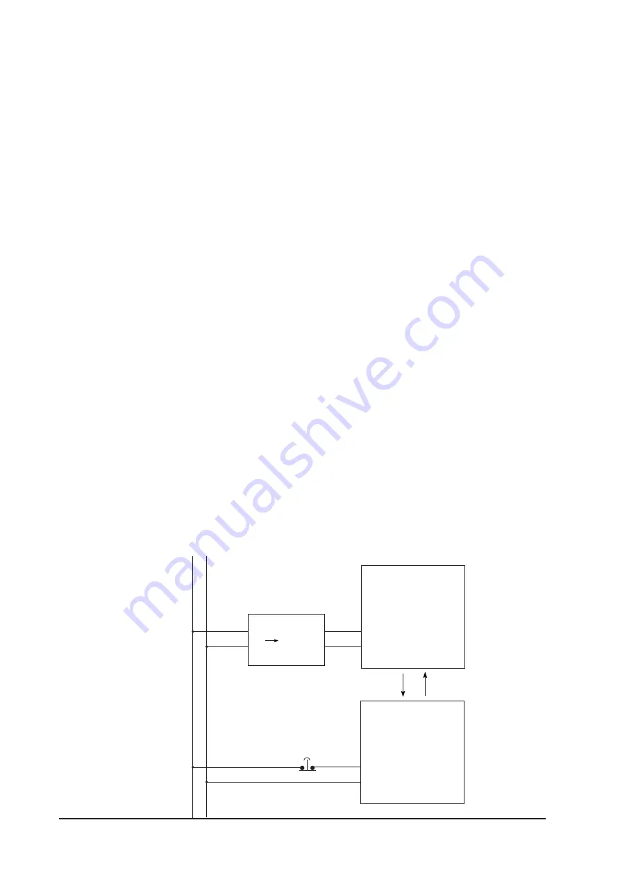
Emergency Stop Circuit
Do NOT send an Emergency Stop signal to the GLC, and do NOT use the GLC
unit’s internal software to process an Emergency Stop signal.
As shown below, be sure to create the Emergency Stop circuit outside the GLC.
GLC
Emergency Stop Button
B contact
Power source
AC
DC 24V
Output
Input
Controlled
System