


91
DENT
Instruments
PowerScout 24
Appendix A
APPENDICES
Appendix A—Connecting Multiple PowerScouts to an RS-485 Network
This section describes setting up a network with multiple PowerScout instruments using the BACnet or
Modbus communication protocol. An RS-485 network can support up to 127 PowerScout 24 meters
connected to a single BACnet client for monitoring and recording power usage at multiple locations
within a single site. Up to 30 PS24 meters may be connected to Modbus.
C
OMMUNICATION
P
ROTOCOL
BACnet MS/TP and Modbus RTU are standard communication protocols that allow for communication
between a client and multiple devices connected to the same network. RS-485 is the protocol standard
used by PowerScout meters as the hardware’s physical interface while BACnet or Modbus is the
networking protocol.
D
AISY
C
HAIN
L
AYOUT FOR
RS-485
N
ETWORK
When multiple devices are connected, the devices need to be connected in a daisy chain. A daisy chain
means that all plus (+) connections are chained together and all minus (-) connections are chained
together across the network.
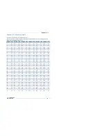
A network containing multiple devices requires a unique address for each device. This allows the master
device to identify and communicate with each slave. The BACnet/Modbus network administrator must
assign a unique network address to each PowerScout 24 using the rotary switches SW1, SW2, and SW3.
Other network layouts, i.e., star, are not recommended when using the RS-485 standard.
N
ETWORKING
U
SING THE
BAC
NET
MS/TP/M
ODBUS
RTU
P
ROTOCOL
1)
Install the RS-485 cable on the RS-485 communications terminal block.
2)
Set a unique address for each device using the table in
Establishing Communication Protocol
in the
Prepping for Field Installation
section.