


45
DENT
Instruments
PowerScout 24
Field Installation
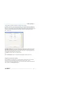
CT
W
IRE
L
EAD
P
OLARITY
CT Type
CT Lead +
CT Lead -
Rogowski (R
ō
Coil)*
White
Brown
Split Core mV
White
Black
Clamp On mV
(1000A clamp, rarely used)
Red
Black
Table 15: CT Polarity
NOTE:
The directionality for Rogowski CTs is the arrow points toward the load (e.g. motor).
* R
ōCoils have a shield wire which must be connected to the meter. This reduces interference and
improves accuracy of the CT.
Connecting Voltage
1)
Connect the voltage leads (L1, L2, L3, and N, as necessary) to the meter. A voltage lead of
14 AWG
THHN Minimum 600VAC rating
(or equivalent in order to maintain 600VAC safety rating of the
device) is required.
2)
Connect the leads to the circuit breaker.
a)
Refer to the wiring diagrams in for wiring
connection specifics. Follow local electrical codes
during this installation.
b)
IMPORTANT:
Verify the breaker is marked as the
disconnect breaker for the meter.
NOTE:
Refer to the Safety Summary in the Introduction
section for information on DC voltage connections.