122
Installing System Components
3
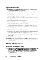
Connect the switch cable to the INTRUSION connector on the system
board (see
Figure 6-1
).
4
Close the expansion card cover (see Figure 3-7).
5
Replace the system cover (see "Installing the System Cover" on page 67).
Power Supply Distribution Module
If your system has redundant power supplies, it will have a power supply
distribution module inside the system.
Removing the Power Supply Distribution Module
1
Turn off the system, including any attached peripherals, and disconnect
the system from the electrical outlet.
2
Remove the redundant power supplies (see "Removing a Redundant Power
Supply" on page 73).
3
Remove the system cover (see "Removing the System Cover" on page 66).
4
Remove the processor airflow shroud (see "Removing the Processor Airflow
Shroud" on page 70).
5
Disconnect all power supply distribution module power cables from the
system board. See Figure 3-31.
6
Pull and hold the blue release pin, slide the module up to free the securing
tabs from the slots, and lift the board out of the chassis (see Figure 3-31).
Summary of Contents for POWEREDGE T300
Page 10: ...10 Contents ...
Page 132: ...132 Installing System Components ...
Page 174: ...174 Jumpers and Connectors ...
Page 176: ...176 Getting Help ...
Page 188: ...188 Glossary ...

