92
Installing System Components
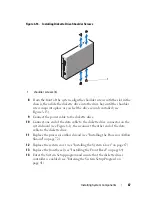
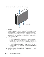
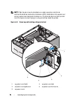
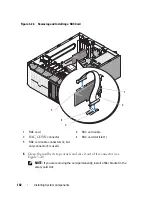
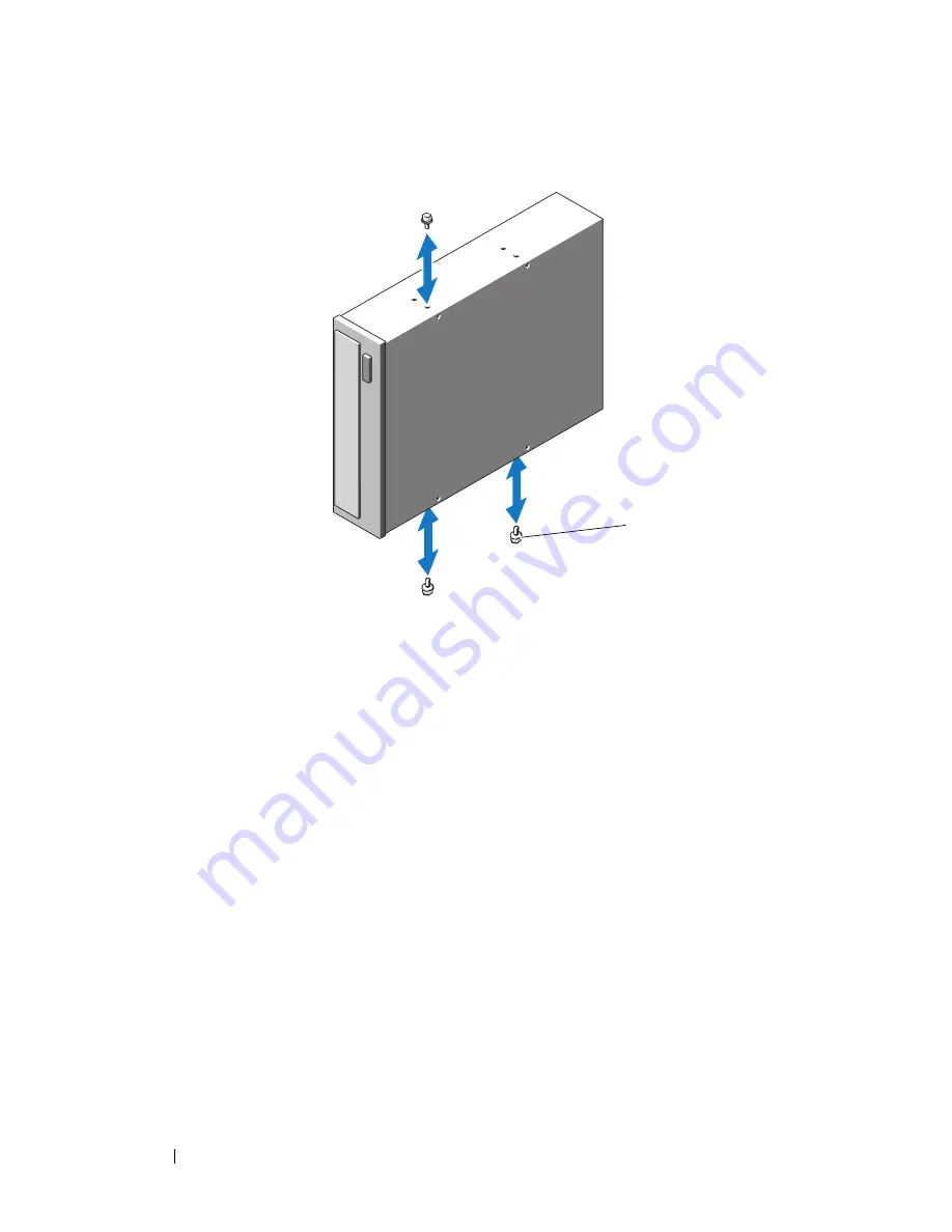
Figure 3-19.
Installing Optical or Tape Drive Shoulder Screws
8
From the front of the system, align the shoulder screws with the slot in the
chassis, then slide the drive into the drive bay until the shoulder screw
snaps into place or you feel the drive securely installed (see Figure 3-18).
9
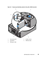
Attach the SCSI power cable (see Figure 3-17) or SATA power cable (see
Figure 3-18) to the drive.
10
Attach the data cable:
•
If you are installing a SATA optical drive (see Figure 3-18), connect
the cable from the SATA connector on the drive to the appropriate
SATA connector on the system board (see "System Board Connectors"
on page 167).
•
If you are installing a SCSI tape drive, connect the SCSI interface
cable (see Figure 3-17) in the drive kit from the SCSI controller card
to the drive.
11
Replace the processor airflow shroud (see "Installing the Processor Airflow
Shroud" on page 72).
1
screws (3)
1
Summary of Contents for POWEREDGE T300
Page 10: ...10 Contents ...
Page 132: ...132 Installing System Components ...
Page 174: ...174 Jumpers and Connectors ...
Page 176: ...176 Getting Help ...
Page 188: ...188 Glossary ...

