background image

Booting to a USB Device 


Memory Key  

1.


Insert the memory key into a USB port and restart the computer.  


2.


When 

F12 = Boot Menu

 appears in the upper-right corner of the screen, press <F12>.  


The BIOS detects the device and adds the USB flash option to the boot menu. 

3.


From the boot menu, select the number that appears next to the USB device.  


The computer boots to the USB device. 

Floppy Drive  

1.


Disable the integrated floppy controller by entering system setup, going to integrated devices, and setting the diskette interface to Off. 


2.

In system setup, go to 

Drive Configuration

 and make sure the 

Diskette Drive A

 option is set to 

3.5 Inch, 1.44 MB


3.

Connect the USB floppy drive, insert a bootable diskette, and re-boot the system. 

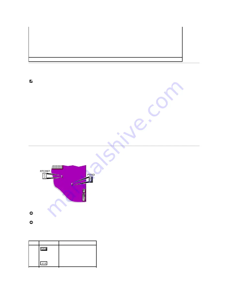
Jumper Settings 


To change a jumper setting, pull the plug off its pin(s) and carefully fit it down onto the pin(s) indicated. 


The acoustics mode field may contain the following options: 

l


Quiet


 The hard drive operates in its quietest setting.  

l


Performance


 The hard drive operates at its maximum speed.  


NOTE: 

Switching to 

Performance

 mode may cause the drive to be noisier, but its performance is not affected.  

l


Bypass

 (default) 

 Your computer does not test or change the current acoustics mode setting.  

l


Suggested


 The hard drive operates at the level suggested by the hard drive manufacturer.  


NOTE: 

Changing the acoustics setting does not alter your hard drive image.  

Asset Tag 


Displays the customer-programmable asset tag number for the computer if an asset tag number is assigned.  

NOTE: 

To boot to a USB device, the device must be bootable. To ensure that your device is bootable, check the device documentation. 

NOTICE: 

Ensure that your computer is turned off and unplugged before you change the jumper settings. Otherwise, damage to your computer or 

unpredictable results can occur. 

NOTICE: 

Before touching anything inside your computer, ground yourself by touching an unpainted metal surface, such as the metal at the back of the 

computer. While you work, periodically touch an unpainted metal surface to dissipate any static electricity that could harm internal components. 

Jumper  Setting 

Description 

PSWD 

 (default) 


Password features are enabled. 

 
Password features are disabled. 

Summary of Contents for OptiPlex SX270

Page 1: ...is product meets the ENERGY STAR guidelines for energy efficiency Other trademarks and trade names may be used in this document to refer to either the entities claiming the marks and names or their products Dell Computer Corporation disclaims any proprietary interest in trademarks and trade names other than its own Model DCT March 2003 P N K0125 Rev A00 Documentation for Your Computer Finding Info...

Page 2: ... match the electromagnetic environment classification of the computer system A Notice About Shielded Signal Cables Use only shielded cables for connecting peripherals to any Dell device to reduce the possibility of interference with radio communications services Using shielded cables ensures that you maintain the appropriate EMC classification for the intended environment For parallel printers a c...

Page 3: ... bottom side or the back panel of your computer or other digital apparatus A statement in the form of IC Class A ICES 003 or IC Class B ICES 003 will be located on one of these labels Note that Industry Canada regulations provide that changes or modifications not expressly approved by Dell could void your authority to operate this equipment CE Notice European Union Marking by the symbol indicates ...

Page 4: ...nfigured when shipped by Dell Any changes you make to this configuration such as installing additional expansion cards or drives may increase the computer s power consumption beyond the limits set by the EPA s ENERGY STAR Computers program ENERGY STAR Emblem The EPA s ENERGY STAR Computers program is a joint effort between the EPA and computer manufacturers to reduce air pollution by promoting ene...

Page 5: ... user may be required to take corrective actions VCCI Class A ITE Regulatory Mark If the regulatory label includes the following marking your computer is a Class A product Class B ITE This is a Class B product based on the standard of the Voluntary Control Council for Interference VCCI for information technology equipment If this equipment is used near a radio or television receiver in a domestic ...

Page 6: ...computer is a Class B product Polish Center for Testing and Certification Notice The equipment should draw power from a socket with an attached protection circuit a 3 prong socket All equipment that works together computer monitor printer and so on should have the same power supply source The phasing conductor of the room s electrical installation should have a reserve short circuit protection dev...

Page 7: ...BSMI Notice Taiwan Only If you find a or mark on the regulatory label on the bottom side or back panel of your computer the following section is applicable ...

Page 8: ...orter Dell Computer Corporation One Dell Way Round Rock TX 78682 Importer Dell Computer de México S A de C V Paseo de la Reforma 2620 11 Piso Col Lomas Altas 11950 México D F Ship to Dell Computer de México S A de C V al Cuidado de Kuehne Nagel de México S de R I Avenida Soles No 55 Col Peñon de los Baños 15520 México D F Model number DCT Supply voltage 12 VDC Input current rating 12 A ...

Page 9: ...Back to Contents Page ...

Page 10: ...Dell Computer Corporation Dell manufactures its hardware products from parts and components that are new or equivalent to new in accordance with industry standard practices For information about the Dell warranty for your computer see the Setup and Quick Reference Guide Back to Contents Page ...

Page 11: ...power saving state press the power button or use the keyboard or the mouse if it is configured as a wake device in the Windows Device Manager For more information about sleep states and exiting from a power saving state see Power Management See Diagnostic Lights for a description of light codes that can help you troubleshoot problems with your computer 3 hard drive access light The hard drive acce...

Page 12: ... adapter connector until the cable snaps securely into place Dell recommends the use of Category 5 wiring and connectors for our customers networks 4 network activity light The yellow light flashes when the computer is transmitting or receiving network data A high volume of network traffic may make this light appear to be in a steady on state 5 power connector The connector for the power adapter 6...

Page 13: ...r computer from the power adapter before removing the cover CAUTION To prevent static damage to components inside your computer discharge static electricity from your body before you touch any of your computer s electronic components You can do so by touching an unpainted metal surface on the computer chassis 1 microprocessor heat sink fan shroud 5 chassis intrusion switch 2 memory modules 6 syste...

Page 14: ...surface 1 Raise the captive screw and slide the chassis stand slat into one of three mounting slots on the back of the computer 2 When the stand is in place tighten the screw NOTICE Do not place your monitor on the computer Use a monitor stand NOTICE In a high vibration environment or when installing the computer overhead use the optional wall mount bracket instead of the chassis stand To order th...

Page 15: ...OTE The stand must not be used in the horizontal position on a desktop Place the computer directly on a desktop 5 mounting slot for vertical position hanging under a surface NOTICE If you are installing the computer under a desktop or tabletop do not attach the cable cover until the computer is firmly attached to the mounting plate see Attaching the Computer to the Mounting Plate NOTE If you use t...

Page 16: ...iagnostic lights see the illustration until it is securely positioned 4 Grasp the top piece of the cable cover and align the two tabs with the two slots in the computer s back panel 5 Insert the tabs into the slots and slide the piece toward the diagnostic lights see the illustration 6 Install a security device in the security cable slot optional Removing the Cable Cover 1 bottom piece of the cabl...

Page 17: ...he cable cover while pressing the lever slide the piece to the left until it stops and then lift it up and away Mounting Plate Attaching the Computer to the Mounting Plate NOTICE When installing the computer in the hanging orientation avoid locations where it will be bumped by a user s legs or chair NOTE Before attaching the mounting plate to a surface first orient yourself with how the stand atta...

Page 18: ...d through the slot in the mounting plate 4 Attach the cable cover if used Removing the Computer From the Mounting Plate 1 Firmly hold the computer and press the release lever tab until the tab is freed from the slot on the mounting plate 1 release lever tab 2 mounting plate slot 3 screw holes 4 4 solid surface with a 1 inch 2 5 cm minimum thickness CAUTION Attach the mounting plate to a solid surf...

Page 19: ...wire to an electrical outlet go to step 4 3 Connect the metal ground connector to the grounding source on the outlet see the following illustration a Loosen the grounding source b Slide the metal ground connector behind the grounding source and then tighten the grounding source 4 Connect the power cable to the outlet Back to Contents Page NOTICE The following section applies to Japan only CAUTION ...

Page 20: ...up and is active Start the Dell Diagnostics from either your hard drive or from the Drivers and Utilities CD also known as the ResourceCD Starting the Dell Diagnostics From Your Hard Drive 1 Shut down and restart the computer 2 When the DELL logo appears press F12 immediately If you wait too long and the Microsoft Windows logo appears continue to wait until you see the Windows desktop Then shut do...

Page 21: ...ch as the keyboard driver come with your Microsoft Windows operating system You may need to install drivers if you l Upgrade your operating system l Reinstall your operating system l Connect or install a new device Option Function Express Test Performs a quick test of devices This test typically takes 10 to 20 minutes and requires no interaction on your part Run Express Test first to increase the ...

Page 22: ...s window click the Hardware tab 5 Click Device Manager 6 Right click the device for which the new driver was installed and click Properties 7 Click the Drivers tab 8 Click Roll Back Driver If Device Driver Rollback does not resolve the problem then use System Restore to return your computer to the operating state that existed before you installed the new driver Using the Drivers and Utilities CD I...

Page 23: ... recover your current Windows XP data type r to select the repair option and then remove the CD from the drive 4 If you want to install a new copy of Windows XP press Esc to select that option 5 Press Enter to select the highlighted partition recommended and then follow the instructions on the screen The Windows XP Setup screen appears and the operating system begins to copy files and install the ...

Page 24: ...program starts automatically exit the program before proceeding 3 Shut down the computer through the Start menu and restart the computer 4 Press F12 immediately after the DELL logo appears If the operating system logo appears wait until you see the Windows desktop and then shut down the computer and try again 5 Press the arrow keys to select CD ROM and then press Enter 6 When the Press any key to ...

Page 25: ...are troubleshooter in the Search field and click the arrow to start the search 3 Click Hardware Troubleshooter in the Search Results list 4 In the Hardware Troubleshooter list click I need to resolve a hardware conflict on my computer and click Next Windows 2000 To resolve incompatibilities using Device Manager 1 Click the Start button point to Settings and then click Control Panel 2 In the Contro...

Page 26: ...and monitors computers and other devices on a corporate network IT Assistant manages assets configurations events alerts and security for computers equipped with industry standard management software It supports instrumentation that conforms to SNMP DMI and CIM industry standards Dell OpenManage Client instrumentation which is based on DMI and CIM is available for your computer For information on ...

Page 27: ...at you use a Kensington lock The documentation that comes with the device contains instructions for installing it Password Protection System Password Option Settings You cannot change or enter a new system password if either of the following two options is displayed l Enabled A system password is assigned l Disabled The system password is disabled by a jumper setting on the system board You can on...

Page 28: ...isable password security Enter password If Password Status is set to Locked Type the password and press Enter If you have assigned a setup password the computer accepts your setup password as an alternate system password If you type a wrong or incomplete system password the following message appears on the screen Incorrect password If you again type an incorrect or incomplete system password the s...

Page 29: ...existing setup password you must know the setup password 1 Enter system setup 2 Type the setup password at the prompt 3 Highlight Setup Password and press the left or right arrow key to delete the existing setup password The setting changes to Not Enabled To assign a new setup password perform the steps in Assigning a System Password 4 Exit system setup Disabling a Forgotten Password and Setting a...

Page 30: ...again System Setup Screens System setup screens display current configuration information for your computer Information on the screen is organized into four areas l Title The box at the top of all screens that lists the computer name l Computer data Two boxes below the title box that display your computer processor L2 cache service tag and the version number of the BIOS l Options A scrollable box ...

Page 31: ...ash Device Insert the memory device into a USB port and restart the computer When F12 Boot Menu appears in the upper right corner of the screen press F12 The BIOS detects the device and adds the USB flash option to the boot menu Changing Boot Sequence for the Current Boot You can use this feature for example to tell the computer to boot from the CD drive so you can run the Dell Diagnostics but spe...

Page 32: ...evice connected to the secondary IDE interface l IDE Drive UDMA The settings are UDMA On default or Off This field enables disables DMA transfers for the internal IDE hard disk interface UDMA This feature can be used to improve data throughput when booting or resuming the operating system If You Have a Problem See Hard drive problems Tape drives are not reflected in the Drive Configuration option ...

Page 33: ...e S3 default or S1 l S3 Maximum power savings l S1 Minimal power savings AC Power Recovery Determines what happens when AC power is restored to the computer l Off default The computer remains off when AC power is restored l On The computer starts when AC power is restored l Last The computer returns to the AC power state existing at the time that AC power was lost l Low Power Mode The options are ...

Page 34: ...rates at its maximum speed NOTE Switching to Performance mode may cause the drive to be noisier but its performance is not affected l Bypass default Your computer does not test or change the current acoustics mode setting l Suggested The hard drive operates at the level suggested by the hard drive manufacturer NOTE Changing the acoustics setting does not alter your hard drive image Asset Tag Displ...

Page 35: ...ds Computer turns off Computer turns off Boots and computer turns on NOTE Pressing or holding the power button to shut down the computer may result in data loss Use the power button to shut down the computer only if the operating system is not responding Action Results Computer Turned On and ACPI Disabled Computer in Suspend Mode Computer Turned Off Press power button Computer turns off immediatel...

Page 36: ...ating system because Windows XP is optimized to take advantage of Hyper Threading technology While many programs can benefit from Hyper Threading some programs have not been optimized for Hyper Threading and may require an update from the software manufacturer Contact the software manufacturer for updates and information about using Hyper Threading with your software To determine if your computer ...

Page 37: ...you must enter system setup and reset the configuration options 1 If you have not already done so make a copy of your configuration information found in system setup see System Setup 2 Remove the cable cover if used 3 Remove the stand if used 4 Remove the computer cover 5 Locate the battery socket labeled BATTERY see System Board Components 6 To remove the battery grip the battery and slightly twi...

Page 38: ...oved 12 Reset the chassis intrusion detector by changing the Chassis Intrusion option to Enabled or Enabled Silent 13 Enter system setup and restore the settings you recorded in step 1 14 Properly dispose of the old battery Back to Contents Page NOTICE To connect a network cable first plug the cable into the network wall jack and then plug it into the computer NOTE If a setup password has been ass...

Page 39: ... if they are misaligned Ensure that fluff from the swab is not left on the rollers 6 Replace the ball and retainer ring and turn the retainer ring clockwise until it clicks into place Floppy Drive Clean your floppy drive using a commercially available cleaning kit These kits contain pretreated floppy disks to remove contaminants that accumulate during normal operation CDs and DVDs If you notice pr...

Page 40: ... center to the outer edge of the disc For stubborn dirt try using water or a diluted solution of water and mild soap You can also purchase commercial products that clean discs and provide some protection from dust fingerprints and scratches Cleaning products for CDs are safe to use on DVDs Back to Contents Page ...

Page 41: ...ule bay Installing a Device When Your Computer Is Turned Off To install a CD DVD device or second hard drive 1 If the module bay is locked open the hard drive door and move the module locking switch to the unlocked position 2 While pressing the module eject button grasp the airbay and pull it out of the module bay NOTICE To prevent damage to devices place them in a safe dry place when they are not...

Page 42: ...y by moving the module locking switch to the locked position 7 Replace the hard drive door Windows XP automatically recognizes the new device 8 If necessary enter your password to unlock your computer Installing a Device When Your Computer Is Running Windows 2000 To install a CD DVD device or second hard drive 1 Click the Unplug or Eject Hardware icon on the taskbar 2 Click the device you want to ...

Page 43: ...u may lock the device in the module bay by moving the module locking switch to the locked position 7 Replace the hard drive door 8 When the operating system recognizes the new device click Close Back to Contents Page ...

Page 44: ...urn them on After you replace the cover the chassis intrusion detector if enabled causes the following message to appear on the screen at the next computer start up ALERT Cover was previously removed 4 Reset the chassis intrusion detector by changing Chassis Intrusion to Enabled or Enabled Silent Back to Contents Page 1 alignment lines NOTICE To connect a network cable first plug the cable into th...

Page 45: ...de the computer cover forward 1 2 inch 1 cm or until it stops and then raise the cover Back to Contents Page CAUTION Before you begin this procedure follow the steps in CAUTION Safety Instructions CAUTION To prevent static damage to components inside your computer discharge static electricity from your body before you touch any of your computer s electronic components You can do so by touching an ...

Page 46: ... make sure the weight of your legs is on your feet and not on the front of your chair seat Adjust your chair s height or use a footrest if necessary to maintain proper posture l Vary your work activities Try to organize your work so that you do not have to type for extended periods of time When you stop typing try to do things that use both hands For more information about ergonomic computing habi...

Page 47: ...Switzerland International Organization for Standardization 1992 Back to Contents Page ...

Page 48: ... and Product Key Label These labels are located on your computer l Latest drivers for my computer l Answers to technical service and support questions l Online discussions with other users and technical support l Documentation for my computer Dell Support Website support dell com The Dell Support website provides several online tools including l Solutions Troubleshooting hints and tips articles fr...

Page 49: ...How to reinstall my operating system Operating System CD After you reinstall your operating system using the Operating System Reinstallation CD use the Drivers and Utilities CD to reinstall drivers for the devices that came with your computer The product key for your operating system is located on your computer ...

Page 50: ... Accessories folder double click the Express Service Code icon and follow the directions For instructions on using the technical support service see Technical Support Service NOTE Some of the following services are not always available in all locations outside the continental U S Call your local Dell representative for information on availability Online Services You can access Dell Support at supp...

Page 51: ...bsite at www dell com For the telephone number to call to speak to a sales specialist see the contact numbers for your region Returning Items for Warranty Repair or Credit Prepare all items being returned whether for repair or credit as follows 1 Call Dell to obtain a Return Material Authorization Number and write it clearly and prominently on the outside of the box For the telephone number to cal...

Page 52: ...ach file Otherwise record the contents of each file before calling Dell Error message beep code or diagnostic code Description of problem and troubleshooting procedures you performed Country City International Access Code Country Code City Code Department Name or Service Area Website and E Mail Address Area Codes Local Numbers and Toll Free Numbers Anguilla General Support toll free 800 335 0031 A...

Page 53: ... 247 9362 TechFax toll free 1 800 950 1329 Customer Care home small business toll free 1 800 847 4096 Customer Care med large business government toll free 1 800 326 9463 Technical Support home small business toll free 1 800 847 4096 Technical Support med large bus government toll free 1 800 847 4096 Sales direct sales from outside Toronto toll free 1 800 387 5752 Sales direct sales from within To...

Page 54: ...ternational Access Code 990 Country Code 358 City Code 9 Website support euro dell com E mail fin_support dell com E mail Support servers Nordic_support dell com Technical Support 09 253 313 60 Technical Support Fax 09 253 313 81 Relational Customer Care 09 253 313 38 Home Small Business Customer Care 09 693 791 94 Fax 09 253 313 99 Switchboard 09 253 313 00 France Paris Montpellier International ...

Page 55: ...cal Support 02 577 826 90 Customer Care 02 696 821 14 Fax 02 696 821 13 Switchboard 02 696 821 12 Corporate Technical Support 02 577 826 90 Customer Care 02 577 825 55 Fax 02 575 035 30 Switchboard 02 577 821 Jamaica General Support dial from within Jamaica only 1 800 682 3639 Japan Kawasaki International Access Code 001 Country Code 81 City Code 44 Website support jp dell com Technical Support se...

Page 56: ...8 202 Corporate Sales toll free 1 800 888 213 Mexico International Access Code 00 Country Code 52 Customer Technical Support 001 877 384 8979 or 001 877 269 3383 Sales 50 81 8800 or 01 800 888 3355 Customer Service 001 877 384 8979 or 001 877 269 3383 Main 50 81 8800 or 01 800 888 3355 Montserrat General Support toll free 1 866 278 6822 Netherlands Antilles General Support 001 800 882 1519 Netherl...

Page 57: ...Support 800 834 077 Customer Care 800 300 415 or 800 834 075 Sales 800 300 410 or 800 300 411 or 800 300 412 or 121 422 07 10 Fax 121 424 01 12 Puerto Rico General Support 1 800 805 7545 St Kitts and Nevis General Support toll free 1 877 441 4731 St Lucia General Support 1 800 882 1521 St Vincent and the Grenadines General Support toll free 1 877 270 4609 Singapore Singapore International Access C...

Page 58: ...011 Technical Support servers toll free 0080 60 1256 Transaction Sales toll free 0080 651 228 or 0800 33 556 Corporate Sales toll free 0080 651 227 or 0800 33 555 Thailand International Access Code 001 Country Code 66 Technical Support toll free 0880 060 07 Customer Service Penang Malaysia 604 633 4949 Sales toll free 0880 060 09 Trinidad Tobago General Support 1 800 805 8035 Turks and Caicos Isla...

Page 59: ...EPP Customers toll free 1 800 695 8133 Projectors Technical Support toll free 1 877 459 7298 Public government education and healthcare Customer Service and Technical Support toll free 1 800 456 3355 Employee Purchase Program EPP Customers toll free 1 800 234 1490 Dell Sales toll free 1 800 289 3355 or toll free 1 800 879 3355 Dell Outlet Store Dell refurbished computers toll free 1 888 798 7561 S...

Page 60: ...t system A program or utility that serves as an interface between the computer hardware and the operating system Unless you understand what effect the settings have on the computer do not change the settings for this program Also referred to as the system setup program bit The smallest unit of data interpreted by your computer Bluetooth A wireless technology standard for short range 9 m 29 feet ne...

Page 61: ...ves Disk striping can speed up operations that retrieve data from disk storage Computers that use disk striping generally allow the user to select the data unit size or stripe width DMA direct memory access A channel that allows certain types of data transfer between RAM and a device to bypass the microprocessor docking device See APR DMTF Distributed Management Task Force A consortium of hardware...

Page 62: ...roprocessor and RAM FTP file transfer protocol A standard Internet protocol used to exchange files between computers connected to the Internet G G gravity A measurement of weight and force GB gigabyte A measurement of data storage that equals 1024 MB 1 073 741 824 bytes When used to refer to hard drive storage the term is often rounded to 1 000 000 000 bytes GHz gigahertz A measurement of frequenc...

Page 63: ...iple keys at the same time Also referred to as a key combination kHz kilohertz A measurement of frequency that equals 1000 Hz L LAN local area network A computer network covering a small area A LAN usually is confined to a building or a few nearby buildings A LAN can be connected to another LAN over any distance through telephone lines and radio waves to form a wide area network WAN LCD liquid cry...

Page 64: ... providing a high speed data path between the microprocessor and devices such as video drives and networks PCMCIA Personal Computer Memory Card International Association The organization that establishes standards for PC Cards PIN personal identification number A sequence of numerals and or letters used to restrict unauthorized access to computer networks and other secure systems PIO programmed in...

Page 65: ...ges Setup program differs from system setup program shortcut An icon that provides quick access to frequently used programs files folders and drives When you place a shortcut on your Windows desktop and double click the icon you can open its corresponding folder or file without having to find it first Shortcut icons do not change the location of files If you delete a shortcut the original file is ...

Page 66: ...s x horizontal pixels by y vertical pixels by z colors Character based software such as text editors displays in video modes that can be defined as x columns by y rows of characters video resolution See resolution virus A program that is designed to inconvenience you or to destroy data stored on your computer A virus program moves from one computer to another through an infected disk software down...

Page 67: ......

Page 68: ...from the plastic door CAUTION Before you begin this procedure follow the steps in CAUTION Safety Instructions CAUTION To guard against electrical shock always unplug your computer from the power supply before removing the hard drive CAUTION To prevent static damage to components inside your computer discharge static electricity from your body before you touch any of your computer s electronic comp...

Page 69: ... to the sled and replace the screws as shown in the illustration 13 Slide the new drive onto the plastic door 14 Attach the drive cable to the connector on the new drive being careful not to bend any of the pins NOTICE Four pins on the hard drive connector do not have corresponding holes on the cable connector Use care when attaching the cable so that the drive pins are not bent or broken ...

Page 70: ... the hard drive by running the Dell Diagnostics 22 Install your operating system on the hard drive For instructions see the documentation that came with your operating system After you replace the cover the chassis intrusion detector if enabled causes the following message to appear on the screen at the next computer start up ALERT Cover was previously removed 23 Reset the chassis intrusion detect...

Page 71: ...n them off now 3 Disconnect any telephone or telecommunication lines from the computer 4 Disconnect your computer and all attached devices from their electrical outlets and then press the power button to ground the system board 5 Remove the computer stand if it is attached NOTICE Before you install new memory modules download the most recent BIOS for your computer from the Dell Support website at ...

Page 72: ...set the chassis intrusion detector by changing Chassis Intrusion to Enabled or Enabled Silent NOTICE Before touching anything inside your computer ground yourself by touching an unpainted metal surface such as the metal at the back of the computer While you work periodically touch an unpainted metal surface to dissipate any static electricity that could harm internal components 1 cutouts 2 2 conne...

Page 73: ...ect any telephone or telecommunication lines from the computer 4 Disconnect your computer and all attached devices from their electrical outlets and then press the power button to ground the system board 5 Remove the computer stand if it is attached 6 Open the computer cover 7 Press out the securing clip at each end of the memory module connector 8 Grasp the module and pull up If the module is dif...

Page 74: ... the fan shroud up and away from the computer CAUTION Before you begin this procedure follow the steps in CAUTION Safety Instructions CAUTION To prevent static damage to components inside your computer discharge static electricity from your body before you touch any of your computer s electronic components You can do so by touching an unpainted metal surface on the computer chassis NOTICE To disco...

Page 75: ...ntly lift the heat sink from the microprocessor 12 Pull the release lever straight up until the microprocessor is released and then remove the microprocessor from the socket 1 tabs two on each securing bracket 2 securing brackets 2 1 heat sink 2 retention base 3 lever NOTICE Lay the heat sink down with the thermal material facing upward NOTICE Be careful not to bend any of the pins when you remove...

Page 76: ...n the microprocessor is fully seated in the socket pivot the release lever back toward the socket until it snaps into place to secure the microprocessor 1 release lever 2 microprocessor 3 socket NOTICE Ground yourself by touching an unpainted metal surface on the back of the computer NOTICE Be careful not to bend any of the pins when you unpack the microprocessor Bending the pins can permanently d...

Page 77: ... plate if used 24 Replace the cable cover if used 25 Connect your computer to the adapter cable and devices to electrical outlets and turn them on After you replace the cover the chassis intrusion detector if enabled causes the following message to appear on the screen at the next computer start up ALERT Cover was previously removed 26 Reset the chassis intrusion detector by changing the Chassis I...

Page 78: ... off the computer before disconnecting a device from the computer l To avoid shorting out your computer when disconnecting a network cable first unplug the cable from the network adapter on the back of your computer and then from the network jack When reconnecting a network cable to your computer first plug the cable into the network jack and then into the network adapter l To help protect your co...

Page 79: ...ion take note of these safety guidelines when appropriate l When you disconnect a cable pull on its connector or on its strain relief loop not on the cable itself Some cables have a connector with locking tabs if you are disconnecting this type of cable press in on the locking tabs before disconnecting the cable As you pull connectors apart keep them evenly aligned to avoid bending any connector p...

Page 80: ...oper or prolonged keyboard use may result in injury CAUTION Viewing the monitor screen for extended periods of time may result in eye strain Battery Disposal Your computer uses a lithium coin cell battery The lithium coin cell battery is a long life battery and it is very possible that you will never need to replace it However should you need to replace it see Battery Do not dispose of the battery...

Page 81: ... and Speaker Problems System Board Problems Video and Monitor Problems Code Cause 1 1 2 Microprocessor register failure 1 1 3 NVRAM 1 1 4 ROM BIOS checksum failure 1 2 1 Programmable interval timer 1 2 2 DMA initialization failure 1 2 3 DMA page register read write failure 1 3 Video Memory Test failure 1 3 1 through 2 4 4 Memory not being properly identified or used 3 1 1 Slave DMA register failur...

Page 82: ... computer starts normally reinstall an additional module Continue until you have identified a faulty module or reinstalled all modules without error l If available install properly working memory of the same type into your computer l If the problem persists contact Dell yellow yellow green yellow A possible expansion card failure has occurred 1 Determine if a conflict exists by removing a card not...

Page 83: ... Diagnostic Lights Blinking green The computer is in the suspended state Microsoft Windows 2000 and Windows XP Press the power button move the mouse or press a key on the keyboard to wake the computer Solid yellow A device on the system board may be faulty or incorrectly installed See Power Problems If the problem persists contact Dell for technical assistance Blinking yellow A power supply or sys...

Page 84: ...s If any of the tests fail contact Dell NOTICE Do not attempt to clean drive heads with a swab You may accidentally misalign the heads which can render the drive inoperable Clean the drive Use a commercially available cleaning kit CAUTION Before you begin any of the procedures in this section follow the steps in CAUTION Safety Instructions Remove and reinstall the floppy drive If the computer disp...

Page 85: ...be corrupt For more information see your operating system documentation Run the Hard Drive Diagnostics Utility The Dell IDE Hard Drive Diagnostics is a utility that tests the hard drive to troubleshoot or confirm a hard drive failure 1 Turn on your computer if your computer is already on restart it 2 When F2 Setup appears in the upper right corner of the screen press Ctrl Alt D 3 Follow the instru...

Page 86: ...and Other Hardware 3 Click Phone and Modem Options 4 Click the Modems tab 5 Click the COM port for your modem 6 Click Properties click the Diagnostics tab and then click Query Modem to verify that the modem is communicating with Windows If all commands receive responses the modem is operating properly Turn off call waiting catch phone See your telephone directory for instructions on deactivating t...

Page 87: ...all the memory modules and if necessary replace them l See Memory Problems for additional troubleshooting suggestions Hard disk configuration error Hard disk controller failure Hard disk drive failure Hard disk drive failure The hard drive failed initialization l Run the Dell Diagnostics l See Hard drive problems for troubleshooting suggestions Insert bootable media The operating system is trying ...

Page 88: ...ubleshooting suggestions Reset failed The disk reset operation failed See Floppy drive problems or Hard drive problems for troubleshooting suggestions Sector not found The operating system cannot locate a sector on the floppy or hard drive l Run the Windows error checking utility to check the file structure on the floppy disk or hard drive See Windows Help for instructions l If a large number of s...

Page 89: ...ve or a zip drive installed see the drive s documentation for instructions Ensure that you have not made an error while entering data See the program documentation to ensure that the values or characters you are entering are valid Check for viruses Use a virus scanning program to check the hard drive floppy disks or CDs Restart the computer Save and close any open files exit any open programs and ...

Page 90: ...ast 8 to 10 seconds until the computer turns off Press the power button again to restart the computer Check the keyboard cable l Ensure that the keyboard cable is firmly connected to the computer l Check the cable connector for bent or broken pins and for damaged or frayed cables Straighten bent pins l Remove keyboard extension cables and connect the keyboard directly to the computer Test the keyb...

Page 91: ...sing a PS 2 mouse 1 Enter system setup and ensure that Mouse Port under the Integrated Devices option is set to On 2 Exit system setup and restart the computer Reinstall the mouse driver See Reinstalling Drivers and Utilities Run the Dell Diagnostics If any of the diagnostics tests fail contact Dell Check for interrupt request conflicts See Resolving Software and Hardware Incompatibilities Check t...

Page 92: ...all any card l Remove and then reinstall the video card if applicable l If the problem persists contact Dell Eliminate interference Electrical appliances on the same circuit or operating near the computer can cause interference Other causes of interference are l Power extension cables l Keyboard and mouse extension cables l Too many devices on a power strip l Multiple power strips connected to the...

Page 93: ...ing for a parallel device matches the recommended settings Check the software documentation If the problem occurs with particular software see the software documentation for the recommended serial or parallel port settings Ensure that the port settings match the recommended settings Run the Dell Diagnostics If the tests do not complete contact Dell Test the device Swap the device with a comparable...

Page 94: ...isconnect them from their electrical outlets wait 10 to 20 seconds and then open the computer cover 2 Rotate the power supply away from the system board 3 Replace the memory module s 4 Close the computer cover reconnect the computer and devices to electrical outlets and then turn them on 5 If the RAM count displayed does not correctly match the actual amount of memory installed in the computer con...

Page 95: ...her electrical devices can cause the screen image to appear shaky Turn off nearby devices to check for interference Adjust the Windows display settings Windows XP 1 Click the Start button and click Control Panel 2 Click Appearance and Themes 3 Click Display and click the Settings tab 4 Try different settings for Screen resolution and Color quality Windows 98 2000 and Windows NT 1 Click the Start b...

Page 96: ...rrupts 23 Computer BIOS 4 Mb flash chip System bus speed 800 533 or 400 MHz quad data rate 200 133 or 100 MHz clock matches external bus speed Network interface controller Gigabit integrated network interface with ASF 1 0 support as defined by DMTF Capable of 10 100 1000 communication Audio Audio type AC97 Sound Blaster emulation optional internal speaker Audio controller Integrated AC97 Codec Ste...

Page 97: ...problem with an installed device solid amber indicates an internal power problem see Power Problems Hard drive access light green light Link integrity light on integrated network adapter green light for 10 Mb operation orange light for 100 Mb operation yellow light for a 1000 Mb 1 Gb operation Activity light on integrated network adapter yellow blinking light Diagnostic lights four yellow and or g...

Page 98: ...ximum shock Operating bottom half sine pulse with a change in velocity of 20 inches sec 50 8 cm sec Storage 27 G faired square wave with a velocity change of 200 inches sec 508 cm sec Altitude Operating 16 to 3048 m 50 to 10 000 ft Storage 16 to 10 600 m 50 to 35 000 ft ...

Page 99: ...er connector FAN2 2 system board speaker SPEAKER 3 speaker connector SPEAKER 4 memory modules DIMM_A and DIMM_B 5 RTC reset jumper RTCRST 6 password jumper PSWD 7 chassis intrusion switch power connector INTRUDER 8 standby power indicator 12V_PWR 9 battery BATTERY 10 fan shroud power connector FAN1 11 microprocessor heat sink ...

Page 100: ...m CD 2 On the Welcome to Microsoft Windows XP screen click Perform additional tasks 3 Under What do you want to do click Transfer files and settings 4 On the Files and Settings Transfer Wizard welcome screen click Next 5 On the Which computer is this screen click Old Computer and click Next 6 On the Select a transfer method screen click the transfer method you prefer 7 On the What do you want to t...

Page 101: ...y last restoration and click Next 3 Click Next The System Restore screen appears and the computer restarts 4 After the computer restarts click OK Enabling System Restore If you reinstall Windows XP with less than 200 MB of free hard disk space available System Restore is automatically disabled To see if System Restore is enabled 1 Click the Start button and click Control Panel 2 Click Performance ...

Page 102: ... back of your computer 2 Connect the other end of the network cable to a network connection device such as a network wall jack Network Setup Wizard The Microsoft Windows XP operating system provides a Network Setup Wizard to guide you through the process of sharing files printers or an Internet connection between computers in a home or small office 1 Click the Start button point to All Programs Ac...

Reviews: