System Board: Dell Latitude E4300 Service Manual
file:///C|/Biz%20Client/2015/Lola%20(Defect%20Fix)/sysboard.htm[5/25/2015 11:14:16 AM]
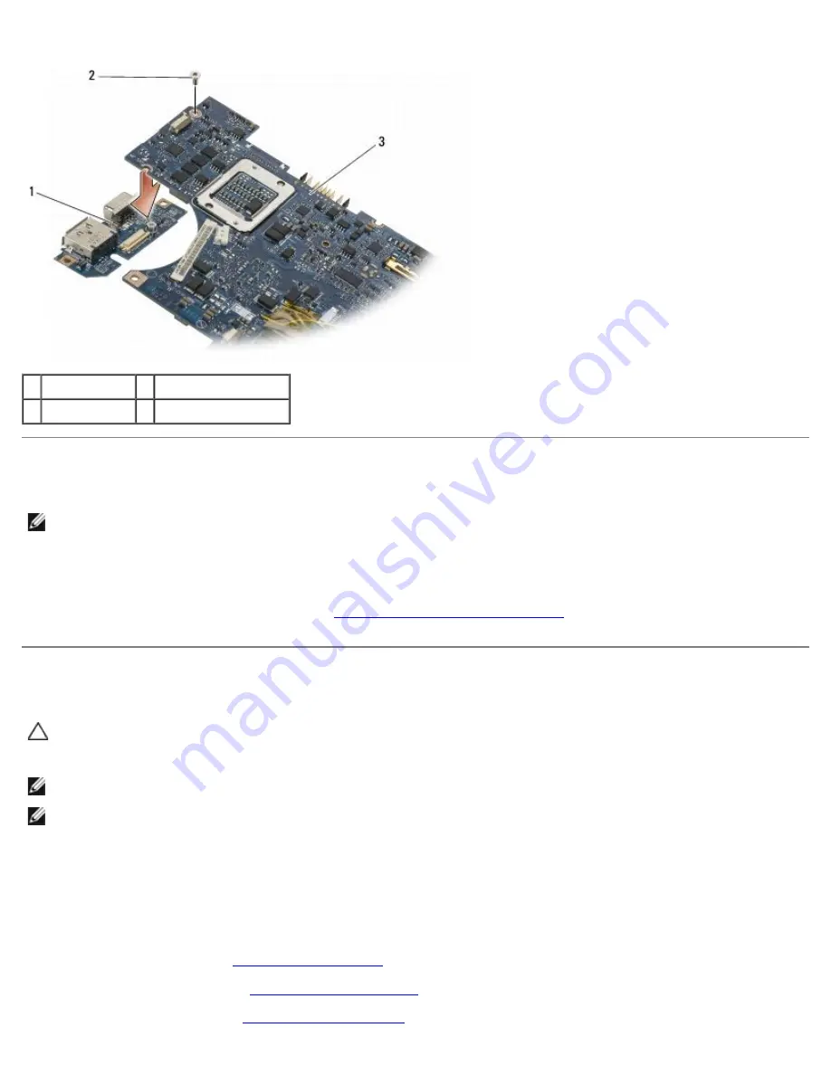
1 left I/O card
2 M2.5 x 5-mm screw
3 system board
Replacing the Left I/O Card
NOTE:
This procedure assumes that you have completed the left I/O card removal procedure first.
1. Reseat the I/O card, aligning the connectors with their respective ports on the left side of the computer base.
2. Replace the M2.5 x 5-mm screw to secure the left I/O card to the computer base.
3. Replace the DC power-cable assembly (see
Replacing the DC-in Power Assembly
).
Replacing the System Board Assembly
CAUTION:
Before working inside the computer, read the safety information that shipped with the
computer. For additional safety best practices information, see the Regulatory Compliance Homepage on
www.dell.com at: www.dell.com/regulatory_compliance.
NOTE:
This procedure assumes that you have completed the removal procedure first.
NOTE:
If you are installing a new system board, the system board kit may or may not include a separate BIOS chip. If
the kit includes a separate BIOS chip, you must install it on the system board before you boot the system.
1. Insert the right side of the system board into the computer base at an angle until the connectors on the system board
are aligned with the holes on the computer base, and then carefully lower the system board into place.
2. Replace the four M2.5 x 5 screws and three M2 x 4-mm screws on the system board.
3. Reconnect the coin-cell battery connector from the bottom side of the computer.
4. Replace the palm rest (see
Replacing the Palm Rest
)
5. Replace the optical drive (see
Replacing the Optical Drive
).
6. Replace the system fan (see
Replacing the System Fan
).


