System Board: Dell Latitude E4300 Service Manual
file:///C|/Biz%20Client/2015/Lola%20(Defect%20Fix)/sysboard.htm[5/25/2015 11:14:16 AM]
www.dell.com at: www.dell.com/regulatory_compliance.
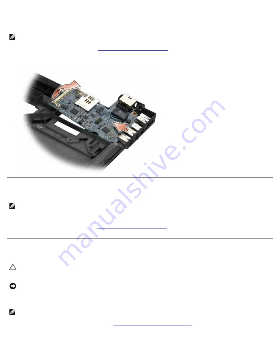
The right I/O card provides USB, audio, and IEEE 1394 connectors for the computer.
NOTE:
This procedure assumes that you have completed the system board removal procedure first.
1. Remove the radio switch board (see
Removing the Radio Switch Board
).
2. Use a scribe under the left side of the I/O card to lift the card from the computer.
Replacing the Right I/O Card
NOTE:
This procedure assumes that you have completed the right I/O card removal procedure first.
1. Reseat the right I/O card, aligning the connectors with their respective ports on the right side of the computer base.
2. Replace the radio switch board (see
Replacing the Radio Switch Board
).
Removing the Left I/O Card
CAUTION:
Before working inside the computer, read the safety information that shipped with the
computer. For additional safety best practices information, see the Regulatory Compliance Homepage on
www.dell.com at: www.dell.com/regulatory_compliance.
NOTICE:
If you are replacing the system board assembly, retain the DC-in power assembly. The DC-in
power assembly is not included with the replacement system board assembly.
The left I/O card provides DC-in, video, and USB connectors.
NOTE:
This procedure assumes that you have completed the system board removal procedure first.
1. Remove the DC power-cable assembly (see
Removing the DC-In Power Assembly
).
2. Remove the M2.5 x 5-mm screw securing the left I/O card to the computer base.
3. Remove the left I/O card from the computer.


