background image

System health and system ID indicator codes........................................................................................................28
NIC indicator codes................................................................................................................................................... 29
Power supply unit indicator codes........................................................................................................................... 29
iDRAC Direct LED indicator codes...........................................................................................................................30

Using system diagnostics................................................................................................................................................30

Dell Embedded System Diagnostics......................................................................................................................... 31

6 Pre-operating system management applications..........................................................................................32

System Setup................................................................................................................................................................... 32

Viewing System Setup.............................................................................................................................................. 32
System Setup details................................................................................................................................................. 32
System BIOS...............................................................................................................................................................33
iDRAC Settings utility................................................................................................................................................ 48
Device Settings.......................................................................................................................................................... 49

Dell Lifecycle Controller...................................................................................................................................................49

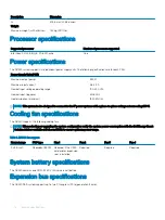
Embedded systems management............................................................................................................................49

Boot Manager...................................................................................................................................................................49

Viewing Boot Manager..............................................................................................................................................49
Boot Manager main menu........................................................................................................................................ 49
One-shot BIOS boot menu.......................................................................................................................................50
System Utilities.......................................................................................................................................................... 50

PXE boot...........................................................................................................................................................................50

7 Jumpers and connectors ..............................................................................................................................51

System board connectors................................................................................................................................................51
System board jumper settings........................................................................................................................................52
Disabling forgotten password......................................................................................................................................... 53

8 Disassembly and reassembly........................................................................................................................54

Safety instructions...........................................................................................................................................................54
Before working inside your system................................................................................................................................ 54
After working inside your system...................................................................................................................................54
Front bezel........................................................................................................................................................................55

Removing the front bezel......................................................................................................................................... 55
Installing the front bezel............................................................................................................................................55

Hard Drives....................................................................................................................................................................... 56

Removing a drive blank............................................................................................................................................. 56
Installing a drive blank................................................................................................................................................57
Removing a drive carrier........................................................................................................................................... 57
Installing a drive carrier............................................................................................................................................. 58
Removing the drive from the drive carrier............................................................................................................. 59
Installing a drive into the drive carrier..................................................................................................................... 60

System cover.................................................................................................................................................................... 61

Removing the system cover......................................................................................................................................61
Installing the system cover....................................................................................................................................... 62

Cooling fans...................................................................................................................................................................... 63

4

Contents

Summary of Contents for NX440

Page 1: ...Dell EMC NX440 Network Attached Storage System Installation and Service Manual Regulatory Model E58S Series Regulatory Type E58S001 ...

Page 2: ...d tells you how to avoid the problem WARNING A WARNING indicates a potential for property damage personal injury or death Revision history Revision Date Description A00 May 2019 Initial release 2019 Dell Inc or its subsidiaries All rights reserved Dell EMC and other trademarks are trademarks of Dell Inc or its subsidiaries Other trademarks may be trademarks of their respective owners 2019 05 Rev A...

Page 3: ...fications 17 Ports and connectors specifications 17 USB ports 18 NIC ports 18 Serial connector 18 VGA ports 18 Environmental specifications 19 Expanded operating temperature 19 Expanded operating temperature restrictions 20 Particulate and gaseous contamination specifications 20 3 Initial system setup and configuration 22 Initialization 22 Setting up your system 22 iDRAC configuration 22 Options f...

Page 4: ...u 49 One shot BIOS boot menu 50 System Utilities 50 PXE boot 50 7 Jumpers and connectors 51 System board connectors 51 System board jumper settings 52 Disabling forgotten password 53 8 Disassembly and reassembly 54 Safety instructions 54 Before working inside your system 54 After working inside your system 54 Front bezel 55 Removing the front bezel 55 Installing the front bezel 55 Hard Drives 56 R...

Page 5: ...the system battery 76 Replacing the optional internal USB memory key 77 Optical drive 78 Removing the optical drive 78 Installing the optional optical drive 78 Processor and heat sink 79 Removing the heat sink 79 Removing the processor 80 Installing the processor 81 Installing the heat sink 82 Drive backplane 83 Removing the drive backplane 83 Installing the drive backplane 84 Power supply unit 85...

Page 6: ...Installing the left control panel 95 Removing the right control panel 96 Installing the right control panel 97 9 Getting help 99 Recycling or End of Life service information 99 Contacting Dell EMC 99 Accessing system information using the QRL 99 Receiving automated support with SupportAssist 100 10 Documentation resources 101 6 Contents ...

Page 7: ... SAS or SATA hard drives Topics Front view of the system Rear view of the system Inside the system Locating the information tag of your system NX440 System Information label Front view of the system Figure 1 Front view of the NX440 system 1 Left control panel 2 Optical drive optional 3 Right control panel 4 Information tag 5 Drives 4 For more information about the ports see Technical specification...

Page 8: ...ion card slot 5 Full height PCIe expansion card slot 6 Power supply unit 1 7 Power supply unit 2 8 System identification button 9 System status indicator cable port CMA 10 USB 3 0 port 2 11 iDRAC9 dedicated network port 12 VGA port For more information about the ports and connectors see Technical specifications 8 System overview ...

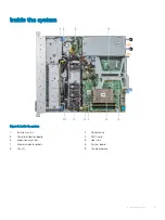
Page 9: ...Figure 3 Inside the system 1 Intrusion switch 2 Optical drive 3 Power distribution board 4 PERC card 5 Expansion card riser 6 Heat sink 7 Memory module sockets 8 System board 9 Fan 4 10 Drive backplane System overview 9 ...

Page 10: ...assis This information is used by Dell to route support calls to the appropriate personnel Figure 4 Locating the information tag of your system 1 Information tag Top view 2 Information tag Bottom view 3 OpenManage Mobile OMM label 4 iDRAC MAC address and iDRAC secure password label NOTE If you have opted for secure default access to iDRAC the iDRAC secure default password is available on the back ...

Page 11: ...NX440 System Information label Labels on the system provide configuration and part replacement instructions Figure 5 Front and rear view configuration Figure 6 Jumper settings System overview 11 ...

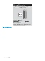
Page 12: ...Figure 7 Memory information 12 System overview ...

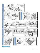
Page 13: ...Figure 8 System information System overview 13 ...

Page 14: ...Figure 9 Electrical overview 14 System overview ...

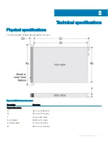
Page 15: ...eight of the system Figure 10 NX440 Chassis dimensions Description Dimension Physical dimensions Xa 482 0 mm 18 98 inches Xb 434 0 mm 17 08 inches Y 42 8 mm 1 68 inches Za with bezel 35 64 mm 1 4 inches Za without bezel 22 0 mm 0 87 inches Zb 534 5 mm 21 04 inches 2 Technical specifications 15 ...

Page 16: ...igned to connect to the IT power systems with a phase to phase voltage not exceeding 230 V Cooling fan specifications The NX440 supports the following cooling fans NOTE When selecting or upgrading the system configuration verify the system power consumption with the Dell Energy Smart Solution Advisor available at Dell com ESSA to ensure optimum power usage Table 1 NX440 fan support Front storage P...

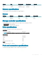
Page 17: ... card and supports external storage using a SAS HBA Internal controller PERC H730P mini External storage 12 Gb SAS Host Bus Adapter card Drive specifications The NX440 system supports SAS and SATA drives and an optical DVD Internal drives 4 x 3 5 inch hot swappable SAS or SATA NOTE Solid State Drives SSDs are supported but must be ordered in a separate kit External storage MD1400 MD1420 12 Gb JBOD...

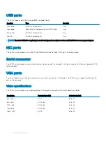
Page 18: ...rts on the back panel Serial connector The NX440 system supports one serial connector on the back panel The serial port is a 9 pin connector Data Terminal Equipment DTE 16550 compliant VGA ports The Video Graphic Array VGA port enables you to connect the system to a VGA display The NX440 system supports one 15 pin VGA port on the back panel Video specifications The NX440 system supports the Integr...

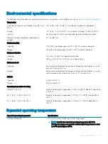
Page 19: ...d Maximum shock Operating Six consecutively executed shock pulses in the positive and negative x y and z axes of 40 G for up to 2 3 ms Storage Six consecutively executed shock pulses in the positive and negative x y and z axes one pulse on each side of the system of 71 G for up to 2 ms Altitude Operating 3 048 m 10 000 ft Storage 12 000 m 39 370 ft Operating temperature de rating Up to 35 C 95 F M...

Page 20: ...greater than 25 W are not supported Tape backup unit is not supported Particulate and gaseous contamination specifications This section defines the limitations that help avoid any equipment damage or failure from particulate and gaseous contamination If the levels of particulate or gaseous pollution exceed the specified limitations and result in equipment damage or failure you may need to rectify ...

Page 21: ...us contamination specifications Gaseous contamination Specifications Copper coupon corrosion rate 300 Å month per Class G1 as defined by ANSI ISA71 04 2013 Silver coupon corrosion rate 200 Å month as defined by ANSI ISA71 04 2013 NOTE Maximum corrosive contaminant levels measured at 50 relative humidity Technical specifications 21 ...

Page 22: ...nd improve the overall availability of Dell systems iDRAC alerts administrators about system issues and enables them to perform remote system management This reduces the need for physical access to the system Options for setting up an iDRAC IP address To enable communication between your system and iDRAC you must first configure the network settings based on your network infrastructure You can set...

Page 23: ...Card The default user name and password are root and calvin NOTE You must have iDRAC credentials to log in to iDRAC For more information see the Integrated Dell Remote Access Control User s Guide located at www dell com idracmanuals You can also access iDRAC using RACADM For more information see the RACADM Command Line Interface Reference Guide located at www Dell com idracmanuals Initial system s...

Page 24: ...partitions on the data drives or their associated physical drives Steps 1 Turn on or restart your system and press F2 to boot into System Setup 2 Click Device Settings 3 Click Integrated RAID Controller 1 Dell PERC PERC H730P Mini Configuration Utility 4 In the Configuration Utility menu click Virtual Disk Management 5 Verify the following Your original Data partition or partitions are shown No OS...

Page 25: ...ve been partitioned External USB DVD ROM is available Windows Storage Server 2016 product key is available This should be attached to the system cover Steps 1 If not completed already restart the system and press F10 Lifecycle Controller 2 In the left navigation pane select OS Deployment The OS Deployment wizard starts 3 On the Select Deployment path page select Go directly to OS Deployment and cl...

Page 26: ... existing data drive for OS installation Make sure the drive selected is the new OS drive created for this purpose 16 In the OS Target Drive option select Unallocated Space the default and click Next The installation begins and takes 60 90 minutes to complete 17 Finish the installation by completing the initial configuration steps described in the product Installation and Service Guide Go to dell ...

Page 27: ...es whether the drive is currently in use or not The status LED indicator indicates the power condition of the drive Figure 11 Drive indicators 1 Drive activity LED indicator 2 Drive status LED indicator 3 Drive capacity label Drive status indicator code Condition Flashes green twice per second Identifying drive or preparing for removal Off Drive ready for removal NOTE The drive status indicator re...

Page 28: ... is healthy and system ID mode is not active Press the system health and system ID button to switch to system ID mode Blinking blue Indicates that the system ID mode is active Press the system health and system ID button to switch to system health mode Solid amber Indicates that the system is in fail safe mode If the problem persists see the Getting help section Blinking amber Indicates that the s...

Page 29: ... is connected to a valid network at less than its maximum port speed and data is being sent or received Link indicator is green and activity indicator is off The NIC is connected to a valid network at its maximum port speed and data is not being sent or received Link indicator is amber and activity indicator is off The NIC is connected to a valid network at less than its maximum port speed and dat...

Page 30: ...rt both 240 V and 120 V input voltages with the exception of Titanium PSUs which support only 240 V When two identical PSUs receive different input voltages they can output different wattages and trigger a mismatch CAUTION If two PSUs are used they must be of the same type and have the same maximum output power iDRAC Direct LED indicator codes The iDRAC Direct LED indicator lights up to indicate t...

Page 31: ...iagnostics 3 Alternatively when the system is booting press F10 select Hardware Diagnostics Run Hardware Diagnostics The ePSA Pre boot System Assessment window is displayed listing all devices detected in the system The diagnostics starts executing the tests on all the detected devices Running the Embedded System Diagnostics from the Dell Lifecycle Controller 1 As the system boots press F10 2 Sele...

Page 32: ...teps 1 Turn on or restart your system 2 Press F2 immediately after you see the following message F2 System Setup NOTE If your operating system begins to load before you press F2 wait for the system to finish booting and then restart your system and try again System Setup details The System Setup Main Menu screen provides the following options NOTE The NX Series systems support only BIOS mode Do no...

Page 33: ...the installed memory Processor Settings Specifies information and options related to the processor such as speed and cache size SATA Settings Specifies options to enable or disable the integrated SATA controller and ports Boot Settings Specifies options to choose the Boot mode and allows you to modify the boot settings Network Settings Specifies options to manage the network settings and boot prot...

Page 34: ...e following options NOTE The NX Series systems support only BIOS mode Do not change the boot mode to UEFI because the system will not load the appliance OS when in UEFI mode Option Description System Model Name Specifies the system model name System BIOS Version Specifies the BIOS version installed on the system System Management Engine Version Specifies the current version of the Management Engin...

Page 35: ...des the following information Option Description System Memory Size Specifies the memory size in the system System Memory Type Specifies the type of memory installed in the system System Memory Speed Specifies the system memory speed System Memory Voltage Specifies the system memory voltage Video Memory Specifies the amount of video memory System Memory Testing Specifies whether the system memory ...

Page 36: ...s or disables the virtualization technology for the processor This option is set to Enabled by default Adjacent Cache Line Prefetch Optimizes the system for applications that need high utilization of sequential memory access This option is set to Enabled by default You can disable this option for applications that need high utilization of random memory access Hardware Prefetcher Enables or disable...

Page 37: ...sh booting and then restart your system and try again 3 On the System Setup Main Menu screen click System BIOS 4 On the System BIOS screen click SATA Settings SATA Settings details The SATA Settings screen details provides the following options Option Description Embedded SATA Enables the embedded SATA option to be set to Off AHCI or RAID modes This option is set to AHCI Mode by default Security F...

Page 38: ... Switching the boot mode may prevent the system from booting if the operating system is not installed in the same boot mode Boot Sequence Retry Enables or disables the Boot Sequence Retry feature If this option is set to Enabled and the system fails to boot the system re attempts the boot sequence after 30 seconds This option is set to Enabled by default Hard Disk Failover Specifies the drive that...

Page 39: ...ts during the boot process depending on the selection After the boot process is complete the USB ports will be enabled or disabled as per the setting NOTE Selecting Only Back Ports On and All Ports Off disables the USB management port and also restricts access to the iDRAC features Internal USB Port Enables or disables the internal USB port This option is set to On or Off This option is set to On ...

Page 40: ...the timer When this option is set to Disabled the default the timer does not have any effect on the system Memory Mapped I O above 4 GB Enables or disables the support for the PCIe devices that require large amount of memory Enable this option only for 64 bit operating systems This option is set to Enabled by default Slot Disablement Enables or disables the available PCIe slots on your system The ...

Page 41: ...tion by SOL configure the same port address for console redirection and the serial device NOTE Every time the system boots the BIOS syncs the serial MUX setting saved in iDRAC The serial MUX setting can independently be changed in iDRAC Loading the BIOS default settings from within the BIOS setup utility may not always revert this setting to the default setting of Serial Device 1 Failsafe Baud Rat...

Page 42: ...available power states This option is set to Enabled by default Memory Refresh Rate Sets the memory refresh rate to either 1x or 2x This option is set to 1x by default Uncore Frequency Enables you to select the Processor Uncore Frequency option Dynamic mode enables the processor to optimize power resources across the cores and uncore during runtime The optimization of the uncore frequency to eithe...

Page 43: ...ocks the system password This option is set to Unlocked by default TPM Security NOTE The TPM menu is available only when the TPM module is installed Enables you to control the reporting mode of the TPM The TPM Security option is set to Off by default You can only modify the TPM Status TPM Activation and the Intel SGX fields if the TPM Status field is set to either On with Pre boot Measurements or ...

Page 44: ...led this setting will hide the Management Engine s ME HECI devices and the system s IPMI devices from the operating system This prevents the operating system from changing the ME power capping settings and blocks access to all in band management tools All management should be managed through out of band This option is set to Enabled by default NOTE BIOS update requires HECI devices to be operation...

Page 45: ...OTE If the password jumper setting is disabled the existing system password and setup password are deleted and you need not provide the system password to boot the system Steps 1 To enter System Setup press F2 immediately after turning on or rebooting your system 2 On the System Setup Main Menu screen click System BIOS System Security 3 On the System Security screen verify that Password Status is ...

Page 46: ...er or Tab 5 In the Setup Password field alter or delete the existing setup password and then press Enter or Tab If you change the system and setup password a message prompts you to reenter the new password If you delete the system and setup password a message prompts you to confirm the deletion 6 Press Esc to return to the System BIOS screen Press Esc again and a message prompts you to save the ch...

Page 47: ...ing options Option Description Redundant OS Location Enables you to select a backup disk from the following devices None IDSDM SATA Ports in AHCI mode BOSS PCIe Cards Internal M 2 Drives Internal USB Redundant OS State NOTE This option is disabled if Redundant OS Location is set to None When set to Visible the backup disk is visible to the boot list and OS When set to Hidden the backup disk is dis...

Page 48: ...ifies the asset tag and enables you to modify it for security and tracking purposes Keyboard NumLock Enables you to set whether the system boots with the NumLock enabled or disabled This option is set to On by default NOTE This option does not apply to 84 key keyboards F1 F2 Prompt on Error Enables or disables the F1 F2 prompt on error This option is set to Enabled by default The F1 F2 prompt also...

Page 49: ...he Dell Lifecycle Controller configuring hardware and firmware deploying the operating system and platform support see the documentation available at the www dell com idracmanuals Boot Manager Use the Boot Manager screen to select boot options and diagnostic utilities Viewing Boot Manager To enter Boot Manager 1 Turn on or restart your system 2 Press F11 when you see the following message F11 Boot...

Page 50: ... the device from which to boot System Utilities System Utilities contains the following utilities that can be launched Launch Diagnostics BIOS Update File Explorer Reboot System PXE boot You can use the Preboot Execution Environment PXE option to boot and configure the networked systems remotely To access the PXE boot option boot the system and then press F12 during POST instead of using standard ...

Page 51: ...s on the system board help to disable the system and setup passwords You must know the connectors on the system board to install components and cables correctly Topics System board connectors System board jumper settings Disabling forgotten password System board connectors The system board inside the NX440 contains the connectors shown in the following diagram Figure 15 System board connectors 7 J...

Page 52: ...d power connector 1 16 FAN4 Fan 4 connector 17 FAN3 Fan 3 connector 18 FAN2 Fan 2 connector 19 TPM TPM connector 20 LEFT_LED Left control panel connector 21 R_INTRUSION Intrusion switch connector 22 IDSDM vFlash IDSDM vFlash connector 23 BATTERY CMOS coin cell battery socket 24 HDD ODD_PWR Optical drive power connector 25 CTRL_PNL Right control panel connector System board jumper settings For info...

Page 53: ...y attached peripherals and disconnect the system from the electrical outlet 2 Remove the 3 Move the jumper on the system board jumper from pins 2 and 4 to pins 4 and 6 4 Install the The existing passwords are not disabled erased until the system boots with the jumper on pins 4 and 6 However before you assign a new system and or setup password you must move the jumper back to pins 2 and 4 NOTE If y...

Page 54: ...product CAUTION To ensure proper operation and cooling all bays in the system and system fans must be always populated with a component or a blank NOTE It is recommended that you always use an antistatic mat and antistatic strap while working on components inside the system Before working inside your system Prerequisite Follow the safety guidelines listed in Safety instructions Steps 1 Power off t...

Page 55: ...on and pull the left end of the bezel 3 Unhook the right end and remove the bezel NOTE The images shown here are for representation only and the actual configuration of your system may vary Figure 16 Removing the front bezel Installing the front bezel To install the front bezel Prerequisite Follow the safety guidelines listed in Safety instructions Steps 1 Locate and remove the bezel key 2 Align a...

Page 56: ...ves Removing a drive blank Prerequisites 1 Follow the safety guidelines listed in Safety instructions 2 If installed remove the front bezel CAUTION To maintain proper system cooling drive blanks must be installed in all empty drive slots CAUTION Mixing drive blanks from previous generations of storage systems is not supported Step Press the release button and slide the drive blank out of the drive...

Page 57: ...stems is not supported Step Insert the drive blank into the drive slot and push the blank until the release button clicks into place Figure 19 Installing a drive blank Next step If removed install the front bezel Removing a drive carrier Prerequisites 1 Follow the safety guidelines listed in Safety instructions 2 If applicable remove the front bezel 3 Use the management software to prepare the dri...

Page 58: ...lacing the drive immediately insert a drive blank in the empty drive slot to maintain proper system cooling Installing a drive carrier Prerequisites CAUTION Before attempting to remove or install a drive while the system is running see the documentation for the storage controller card to ensure that the host adapter is configured correctly to support drive removal and insertion CAUTION Mixing driv...

Page 59: ...ith the backplane 3 Close the drive carrier release handle to lock the drive in place Figure 21 Installing a drive carrier Next step If applicable install the front bezel Removing the drive from the drive carrier Prerequisite CAUTION Mixing drives from previous generations of storage systems is not supported Steps 1 Using Phillips 1 screwdriver remove the screws from the slide rails on the drive c...

Page 60: ...torage systems is not supported Steps 1 Insert the drive into the drive carrier with the connector end of the drive towards the back of the carrier 2 Align the screw holes on the drive with the screws holes on the drive carrier When aligned correctly the back of the drive is flush with the back of the drive carrier 3 Using the Phillips 1 screwdriver secure the drive to the drive carrier with screw...

Page 61: ...connect the system from the electrical outlet and disconnect the peripherals Steps 1 Using a 1 4 inch flat head or a Phillips 2 screwdriver rotate the latch release lock counter clockwise to the unlocked position 2 Lift the latch till the system cover slides back and the tabs on the system cover disengage from the guide slots on the system 3 Hold the cover on both sides and lift the cover away fro...

Page 62: ... the system cover with the guide slots on the system 2 Push the system cover latch down The system cover slides forward the tabs on the system cover engage with the guide slots on the system and the system cover latch locks into place 3 Using a 1 4 inch flat head or Phillips 2 screwdriver rotate the latch release lock clockwise to the locked position NOTE The images shown here are for representati...

Page 63: ...g any attached peripherals Cooling fans The cooling fan components include a cooling fan blank and the cooling fan Both parts are replaceable Removing the cooling fan blank 1 Press the release tab to disengage the blank from the cooling fan cage 2 Lift the cooling fan blank out of the fan cage Figure 26 Removing a fan blank Disassembly and reassembly 63 ...

Page 64: ...ing fan Prerequisites Follow the safety guidelines listed in Safety instructions Follow the procedures in Before working inside your system Remove the air shroud Steps 1 Press the release tabs on the fan cable connector and disconnect the cable from the system board NOTE Observe the routing of the cable as you remove it from the system 2 Lift the cooling fan out of the cooling fan cage 64 Disassem...

Page 65: ... the safety guidelines listed in Safety instructions 2 Follow the procedures in Before working inside your system Steps 1 Lower the cooling fan into the cooling fan cage 2 Press the release tabs on the fan cable connector and connect the cable from the system board NOTE Route the cable properly to prevent the cable from being pinched or crimped Disassembly and reassembly 65 ...

Page 66: ... Follow the safety guidelines listed in Safety instructions 2 Follow the procedures in Before working inside your system 3 Keep the plastic scribe ready Steps 1 Disconnect and remove the intrusion switch cable NOTE Observe the routing of the cable as you remove it from the system 2 Using a plastic scribe slide the intrusion switch out of the intrusion switch slot 66 Disassembly and reassembly ...

Page 67: ...ures in Before working inside your system Steps 1 Align and insert the intrusion switch in the slot until it locks in the slot on the chassis NOTE Route the cable through the cable routing tab when you replace it to prevent the cable from being pinched or crimped 2 Connect the intrusion switch cable to the connector on the system board Figure 31 Installing the intrusion switch Disassembly and reas...

Page 68: ...emory module socket 2 To release the memory module from the socket simultaneously press the ejectors on both ends of the memory module socket CAUTION Handle each memory module only by the card edges ensuring not to touch the middle of the memory module or metallic contacts 3 Lift the memory module away from the system Figure 32 Removing a memory module Next step 1 Install the memory module or if y...

Page 69: ...u to install the memory module in the socket in only one orientation CAUTION Do not apply pressure at the center of the memory module apply pressure at both ends of the memory module evenly 4 Press the memory module with your thumbs until the socket levers firmly click into place When the memory module is properly seated in the socket the levers on the memory module socket align with the levers on...

Page 70: ...oving the air shroud Prerequisite CAUTION Never operate your system with the air shroud removed Without the air shroud the system may overheat resulting in shutdown of the system and loss of data 1 Follow the safety guidelines listed in Safety instructions Step Using the blue touch points lift the air shroud out of the system Figure 34 Removing the air shroud Installing the air shroud Prerequisite...

Page 71: ...roud Steps 1 Open the expansion card riser latch 2 Holding the blue touch points lift the expansion card riser from the system Figure 36 Removing the expansion card riser 3 If you are removing the riser permanently install a filler bracket in the empty expansion slot and close the expansion card latch 4 Using a Philips 2 screw driver tighten the screw to secure the filler bracket to the system Dis...

Page 72: ... instructions 2 Follow the procedures in Before working inside your system 3 Remove the air shroud 4 If removed Install the expansion card into the riser 5 Open the expansion card riser latch Steps 1 Align the guide on the expansion card riser with the guide pin on the system board and lower the riser until it is firmly seated 2 Close the expansion card riser latch 72 Disassembly and reassembly ...

Page 73: ...side your system 3 Disconnect any cables connected to the expansion card or expansion card riser 4 Remove the expansion card riser Steps 1 Flip the expansion card riser to locate the connectors on the riser 2 Holding the card by its edges remove the expansion card from the expansion card riser Figure 39 Removing the expansion card from the expansion card riser 3 If you are removing the card perman...

Page 74: ...king inside your system 3 Remove the expansion card riser 4 If installed remove the filler bracket Steps 1 Flip the expansion card riser to locate the connectors on the riser 2 Holding the card by its edges align and insert the expansion card in the connector on the expansion card riser 3 If applicable connect the cables to the expansion card Figure 41 Installing the expansion card in the expansio...

Page 75: ...latch to disengage it from the PERC card 3 Push the blue release latch until the tab clicks into the slot on the system 4 Hold the PERC card by the edges and pull it to disengage it from the PERC card slot 5 Flip the PERC card and disconnect the cable from the PERC card Figure 42 Removing the PERC card Next step 1 Install the PERC card Installing the PERC card Prerequisites 1 Follow the safety gui...

Page 76: ... danger of a new battery exploding if it is incorrectly installed Replace the battery only with the same or equivalent type recommended by the manufacturer Discard used batteries according to the manufacturer s instructions Follow the safety guidelines listed in Safety instructions Follow the procedures in Before working inside your system Steps 1 Locate the battery socket For more information see...

Page 77: ...ns of the USB memory key are 15 9 mm wide x 57 15 mm long x 7 9 mm high 1 Follow the safety guidelines listed in Safety instructions 2 Follow the procedures in Before working inside your system 3 Remove expansion card riser Steps 1 Locate the USB port or USB memory key on the system board To locate the USB port see the system board connectors section 2 If installed remove the USB memory key from t...

Page 78: ...system Figure 46 Removing the optical drive Next step 1 Install the optical drive or optical drive blank NOTE Blanks must be installed on empty optical drive slot to maintain FCC certification of the system The brackets also keep dust and dirt out of the system and aid in proper cooling and airflow inside the system Installing the optional optical drive The procedure for installing an optical driv...

Page 79: ...ocessor first remove the heat sink to gain access to the processor Removing the heat sink Prerequisites 1 Follow the safety guidelines listed in Safety instructions 2 Follow the procedures in Before working inside your system 3 Remove the air shroud WARNING The heat sink and processor are too hot to touch for some time after the system has been powered down Allow the heat sink and processor to coo...

Page 80: ...our system 3 Remove the air shroud 4 Remove the heat sink Steps 1 Release the socket lever by pushing the lever down and out from under the tab on the processor shield 2 Lift the lever upward to lift the processor shield CAUTION Do not touch the processor socket pins they are fragile and can be permanently damaged Be careful not to bend the pins in the processor socket when removing the processor ...

Page 81: ...cessor with the triangle on the system board CAUTION Do not use force to seat the processor When the processor is positioned correctly it engages easily into the socket 2 Place the processor in the socket 3 Close the processor shield by sliding it under the retention screw 4 Lower the socket lever and push it under the tab to lock it Figure 50 Installing the processor Next steps 1 Install the heat...

Page 82: ... thermal grease can result in excess grease coming in contact with and contaminating the processor socket NOTE The thermal grease syringe is intended for one time use only Dispose the syringe after you use it Figure 51 Applying thermal grease on top of the processor 3 Align the heat sink with the standoff screws on the system board CAUTION When installing the heat sink ensure that the airflow arro...

Page 83: ...porarily label them before removal so that you can replace them in the same drive slots 1 Follow the safety guidelines listed in Safety instructions 2 Follow the procedures in Before working inside your system 3 Remove the drives 4 Disconnect the following cables from the backplane a Backplane signal cable b Backplane power cable c PERC cable NOTE Observe the routing of the cable as you remove it ...

Page 84: ...s 2 Follow the procedures in Before working inside your system 3 Remove the drives NOTE To avoid damaging the backplane ensure to move the control panel cables from the cable routing clips before removing the backplane NOTE Route the cable properly when you replace it to prevent the cable from being pinched or crimped Steps 1 Align the slots on the backplane with the hooks on the system 2 Lower th...

Page 85: ...side your system Power supply unit Removing a power supply unit blank Prerequisite 1 Follow the safety guidelines listed in Safety instructions Step Pull the blank out of the system CAUTION To ensure proper system cooling the power supply unit blank must be installed in the second power supply unit bay in a non redundant configuration Remove the power supply unit blank only if you are installing a...

Page 86: ...moving a power supply unit Prerequisites CAUTION The system needs one power supply unit PSU for normal operation On power redundant systems remove and replace only one PSU at a time in a system that is powered on 1 Follow the safety guidelines listed in Safety instructions 2 Disconnect the power cable from the power source and from the PSU you intend to remove and then remove the cable from the st...

Page 87: ...lling a power supply unit Prerequisites 1 Follow the safety guidelines listed in Safety instructions 2 For systems that support redundant PSU ensure that both the PSUs are of the same type and have the same maximum output power NOTE The maximum output power shown in watts is listed on the PSU label Step Push the PSU into the slot on the system until the release latch snaps into place Disassembly a...

Page 88: ...ete Wait until the new PSU is discovered and enabled before you remove the other PSU The PSU status indicator turns green to signify that the PSU is functioning properly Power distribution board Removing the power distribution board Prerequisites 1 Follow the safety guidelines listed in Safety instructions 2 Follow the procedures in Before working inside your system 3 Remove the power supply units...

Page 89: ...fore working inside your system Steps 1 Align the power distribution board PDB with the standoffs on the system 2 Using a Philips 2 screwdriver tighten the screws that secure the PDB to the system 3 Connect the cables to the system board and the drive backplane NOTE Route the cable properly when you replace it to prevent the cable from being pinched or crimped Figure 60 Installing the power distri...

Page 90: ...in Before working inside your system 3 Remove the following components a Air shroud b Memory Modules c Disconnect the fan cable d Expansion card riser e Storage controller card f Heat sink and processor CAUTION To prevent damage to the processor socket when replacing a faulty system board ensure that you cover the processor socket with the processor dust cover g Internal USB if installed h If appl...

Page 91: ...ystem board holder slightly lift the system board and then slide it toward the front of the chassis 4 Lift the system board out of the chassis Figure 62 Removing the system board Next step 1 Install the system board Disassembly and reassembly 91 ...

Page 92: ... the screws that secure the system board to the chassis Next steps 1 Replace the following a TPM Module NOTE The TPM Module must be replaced only while installing new system board b Storage controller card c Internal USB key if applicable d Expansion card and riser e Processor and heat sink f Memory modules g Air shroud 2 Reconnect the cables to the system board NOTE Ensure that the cables inside ...

Page 93: ...prompted to create a recovery key during program or System Setup Work with the customer to create and safely store this recovery key When replacing this system board you must supply the recovery key when you restart your system or program before you can access the encrypted data on your hard drives CAUTION After the TPM plug in module is installed it is cryptographically bound to that specific sys...

Page 94: ...em BIOS System Security Settings 9 From the Intel TXT option select On Initializing the TPM 2 0 for TXT users 1 While booting your system press F2 to enter System Setup 2 On the System Setup Main Menu screen click System BIOS System Security Settings 3 From the TPM Security option select On 4 Save the settings 5 Restart your system 6 Enter System Setup again 7 On the System Setup Main Menu screen ...

Page 95: ...om the system 2 Using the appropriate screwdriver loosen the screws that secure the left control panel 3 Hold the left control panel assembly and remove it from the system Figure 65 Removing the left control panel Next steps 1 Install the left control panel 2 Follow the procedures in After working inside your system Installing the left control panel Prerequisites 1 Follow the safety guidelines lis...

Page 96: ...e left control panel Next step 1 Follow the procedures in After working inside your system Removing the right control panel Prerequisites 1 Follow the safety guidelines listed in Safety instructions 2 Follow the procedures in Before working inside your system Steps 1 Disconnect the control panel cable from the connector on the system board NOTE Observe the routing of the cable as you remove it fro...

Page 97: ...ol panel cable through the side wall and the guide slots in the system NOTE Route the cable properly to prevent the cable from being pinched or crimped 2 Align and insert the right control panel assembly in the slot on the system 3 Using the appropriate screwdriver tighten the screws that secure the right control panel 4 Connect the control panel cable to the connector on the system board Disassem...

Page 98: ...Figure 68 Installing the right control panel Next step 1 Follow the procedures in Before working inside your system 98 Disassembly and reassembly ...

Page 99: ...ervice Tag field b Click Submit The support page that lists the various support categories is displayed 4 For general support a Select your product category b Select your product segment c Select your product The support page that lists the various support categories is displayed 5 For contact details of Dell EMC Global Technical Support a Go to Dell com support incidents online b The Contact Tech...

Page 100: ...monitors your Dell EMC devices and automatically detects hardware issues both proactively and predictively Automated case creation When an issue is detected SupportAssist automatically opens a support case with Dell EMC Technical Support Automated diagnostic collection SupportAssist automatically collects system state information from your devices and uploads it securely to Dell EMC This informati...

Page 101: ...tures configuring and logging in to iDRAC and managing your system remotely see the Integrated Dell Remote Access Controller User s Guide www dell com idracmanuals For information about understanding Remote Access Controller Admin RACADM subcommands and supported RACADM interfaces see the RACADM Command Line Reference Guide for iDRAC www dell com idracmanuals For information about updating drivers...

Page 102: ...ww dell com omconnectionsenterprisesystemsmanagement For information about connections and client systems management see the OpenManage Connections Client Systems Management documentation www dell com dellclientcommandsuitemanuals Working with the Dell EMC PowerEdge RAID controllers For information about understanding the features of the Dell PowerEdge RAID controllers PERC and deploying the PERC ...

Reviews: