background image

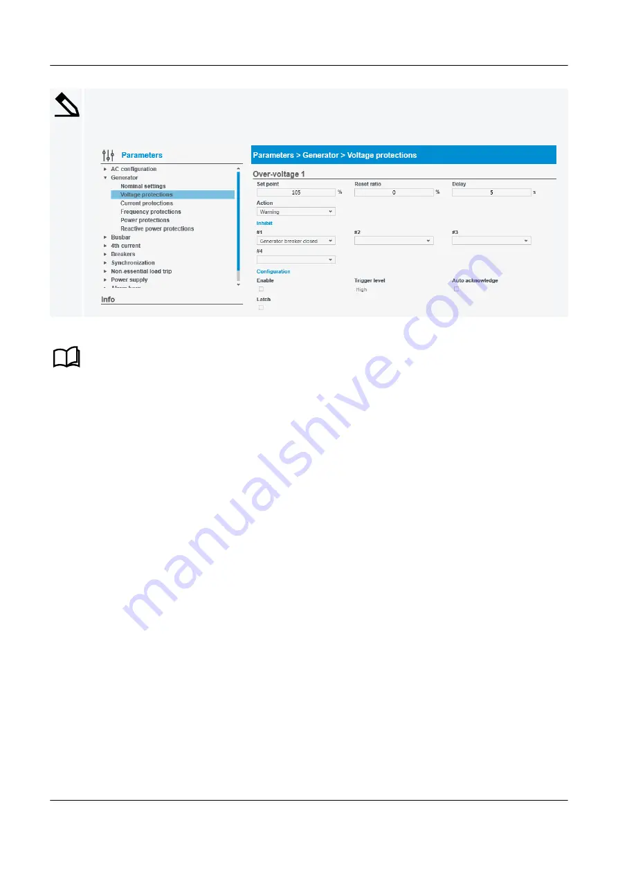
Controller alarm protection example

The setting for the 

Over-voltage 1

 alarm is found under:

Configure > Parameters > Generator > Voltage protections

See 

Protections

 in the 

Designer’s handbook

 for more information on alarms and alarm parameter settings.

PPM 300 PICUS manual 4189341080 UK

www.deif.com

Page 103 of 213

Summary of Contents for PICUS PPM 300

Page 1: ...x 45 9614 9615 info deif com www deif com isenborgvej 33 DK 7800 Skive Tel 45 9614 9614 Fax 45 9614 9615 info deif com www deif com 14 9614 Fax 45 9614 9615 info deif com www deif com PICUS MANUAL Protection and Power Management PPM 300 Document no 4189341080C ...

Page 2: ...System requirements 14 2 2 Download 14 2 2 1 Downloading PICUS 14 2 3 Installation 17 2 3 1 Installation prerequisites 17 2 3 2 Install PICUS 17 2 4 Ethernet connection 21 2 4 1 Connect your computer 21 2 5 Launch 22 2 5 1 Launching PICUS 22 2 6 PICUS overview 22 2 6 1 Screen layout 22 2 6 2 Regional settings 24 2 6 3 About information 25 2 6 4 Notifications 26 3 Connection 3 1 Introduction 29 3 1...

Page 3: ...ew blank user 49 5 3 10 Create a new copied user 50 5 3 11 Edit a user 50 5 3 12 Delete a user 50 5 3 13 Write users to the controller 50 5 3 14 Broadcast users to selected controller s 51 6 Single line diagram 6 1 Introduction 53 6 1 1 Introduction 53 6 1 2 Components 53 6 1 3 Busbar colours 59 6 1 4 Diagram icons 59 6 2 Page layout 60 6 2 1 Single line page 60 6 3 Tasks 61 6 3 1 Configure the si...

Page 4: ...0 7 7 Tasks 93 7 7 1 Configure the terminal name 93 7 7 2 Configure custom alarm s 93 7 7 3 Configure function s 95 7 7 4 Configure the relay setup 95 7 7 5 Configure the sensor setup 97 7 7 6 Configure the output setup 99 8 Parameters 8 1 Introduction 102 8 1 1 Introduction 102 8 2 Page layout 104 8 2 1 Parameters page 104 8 3 Tasks 105 8 3 1 Configure parameters 105 9 CustomLogic 9 1 Introductio...

Page 5: ...137 9 6 4 Example 4 Power management rules dependent on bus tie breaker position 141 10 Live data 10 1 Introduction 145 10 1 1 Introduction 145 10 1 2 Views 145 10 2 Page layout 149 10 2 1 Live data page 149 10 3 Tasks 150 10 3 1 View Live data 150 11 Supervision 11 1 Introduction 152 11 1 1 Introduction 152 11 1 2 Busbar colours 152 11 1 3 Diagram icons 152 11 2 Page layout 153 11 2 1 Supervision...

Page 6: ...14 3 3 Simulate input output 172 14 3 4 Emulator options 173 15 Backups 15 1 Introduction 174 15 1 1 Introduction 174 15 1 2 Backing up information 174 15 1 3 Back up or restore restrictions 174 15 2 Page layout 175 15 2 1 Backup page 175 15 2 2 Restore page 176 15 3 Tasks 177 15 3 1 Back up or restore a configuration 177 15 3 2 Create a backup file 177 15 3 3 Restore or broadcast from a folder 17...

Page 7: ...laying 196 18 3 Firmware 196 18 3 1 Firmware update issues 196 18 4 Files 197 18 4 1 Unable to locate file s 197 18 5 Broadcast 198 18 5 1 Unsuccessful broadcast attempt s 198 19 Glossary 19 1 Terms and abbreviations 199 19 1 1 Terms and abbreviations 199 19 2 Units 203 19 2 1 Units 203 19 3 Symbols 204 19 3 1 Symbols for notes 204 19 3 2 Menus and icon symbols 205 19 3 3 Single line symbols 209 1...

Page 8: ...dling Emulation of the system Updating and applying firmware Creating and restoring backup files Working on an offline project 1 2 About the PICUS manual 1 2 1 General purpose This is the PICUS manual for DEIF s Power in Control Utility Software The PICUS manual provides information and guidance to use the utility software with the ML 300 controllers 1 2 2 Intended users of the PICUS manual The PI...

Page 9: ...ram Configure Single line See Single line diagram for more information Configure input output settings Configure Input output See Input outputs for more information Configure parameter settings Configure Parameters See Parameters for more information Configure CustomLogic Configure CustomLogic See CustomLogic for more information Table 1 2 Operation and supervision Task Location View or action ala...

Page 10: ...ication 1 0 5 x PICUS PC software 1 0 3 x 1 2 5 Technical support You can read about service and support options on the DEIF website www deif com You can also find contact details on the DEIF website You have the following options if you need technical support Help The display unit includes context sensitive help Technical documentation Download all the product technical documentation from the DEI...

Page 11: ...Protections and alarms Breakers synchronisation and de loading Regulation Power management Each controller type Principles sequences functions and protections Hardware characteristics and configuration PICUS including permissions CustomLogic Emulation Modbus Installation instructions Tools and materials Mounting Minimum wiring for each controller type Wiring for hardware module terminals Wiring fo...

Page 12: ...t the same time in addition to display units for each controller You must therefore ensure that a controller does not simultaneously receive conflicting information from PICUS and or the display units especially during commissioning and servicing Simultaneous configuration changes example If two conflicting configuration changes are made simultaneously using PICUS and the display unit respectively...

Page 13: ...t contains open source software licensed under for example the GNU General Public License GNU GPL and GNU Lesser Public License GNU LGPL The source code for this software can be obtained by contacting DEIF at support deif com DEIF reserves the right to charge for the cost of the service 1 4 3 Trademarks DEIF power in control and the DEIF logo are trademarks of DEIF A S Modbus is a registered trade...

Page 14: ...res a DirectX10 graphics card Browser Internet Explorer 8 9 10 or 11 Mozilla Firefox 10 x or a later version Apple Safari 5 Google Chrome 17 x PDF save PDF document software such as DoPdf or CutePDF Creates PDF document from the report data PDF reader Acrobat Reader 8 0 or higher To read PDF report CAUTION Due to the way that Windows allows access to network files and folders it may not be possibl...

Page 15: ...load PICUS please follow the following steps 1 Visit the DEIF website at www deif com 2 Select Software 3 Under Software select Software download PPM 300 PICUS manual 4189341080 UK www deif com Page 15 of 213 ...

Page 16: ...bmit your email address to receive a download link to the software 6 Follow the link in the email to download PICUS to your computer INFO Direct link to software downloads http www deif com software software download PPM 300 PICUS manual 4189341080 UK www deif com Page 16 of 213 ...

Page 17: ... see Troubleshooting Connections for more information and assistance 2 3 2 Install PICUS Install PICUS INFO Ensure you have closed any running version of PICUS before installing or reinstalling INFO DEIF recommends that you close all other applications before installing CAUTION You must install Bonjour if you do not already have this installed on your computer This service is used for the network ...

Page 18: ...necessary by using Browse and selecting a desired folder location Select Next to proceed to the next step 3 Confirm the start menu folder for PICUS shortcuts INFO It is recommended to leave this as the default location Change the default if required Select Next to proceed to the next step PPM 300 PICUS manual 4189341080 UK www deif com Page 18 of 213 ...

Page 19: ...ext to proceed to the next step 5 You are now ready to install PICUS If you wish to make any changes to the installation settings use the Back button to return to a previous step Select Install to start the installation process PPM 300 PICUS manual 4189341080 UK www deif com Page 19 of 213 ...

Page 20: ... have installed PICUS on your computer or use the desktop shortcut created by the installer INFO Depending upon the security settings of your computer you may see a Windows User Account Control UAC notification shield on the desktop shortcut Launching PICUS displays a UAC confirmation prompt select Yes to launch PICUS PPM 300 PICUS manual 4189341080 UK www deif com Page 20 of 213 ...

Page 21: ...Ethernet cable requirements INFO DEIF recommends using PCM port 3 although you can use any free Ethernet port on the PCM or display unit Figure 2 1 Example recommended connection Service PC PICUS PCM3 1 Controller 3 PSM3 1 Multi line 300 EtherCAT CAUTION It is recommended to directly connect your computer to one of the controllers Connection via a network or USB network adaptor may cause loss of c...

Page 22: ...n also add a shortcut to the desktop You can launch PICUS from the desktop icon Default folder location can vary by the operating system you are using 2 6 PICUS overview 2 6 1 Screen layout The basic layout for PICUS is shown below The layout for each page is shown at the beginning of each section in this document for easy reference INFO The available features shown in PICUS depend upon the permis...

Page 23: ...label Generator status 4 Window controls Minimise maximise with taskbar maximise full screen or close PICUS 5 About PICUS Software operating system and support contact information 6 Additional page content Additional information for the selected page 7 Right side panel Additional menu or actions for the selected page 8 Page icons Page icons or actions PPM 300 PICUS manual 4189341080 UK www deif co...

Page 24: ... Create and print report Access advanced features View or configure group and user permissions Apply firmware upgrade Configure View or configure single line diagram Access emulation View or configure input output settings View or configure parameter settings View or configure CustomLogic These pages can be restricted by the permissions of the logged on user profile 2 6 2 Regional settings PICUS u...

Page 25: ...ttings before configuring any values 2 6 3 About information You can view the about information by selecting the DEIF logo from any page This displays the about information page INFO The about information can be useful for if you need to contact DEIF support for assistance PPM 300 PICUS manual 4189341080 UK www deif com Page 25 of 213 ...

Page 26: ...information Shows details for the connected and logged on controller 4 Contact and support Shows DEIF s contact and support information including a direct link to the DEIF helpdesk 2 6 4 Notifications Information notification blue During operation you can be advised about events that occur with a blue notification window PPM 300 PICUS manual 4189341080 UK www deif com Page 26 of 213 ...

Page 27: ...the information 2 Close Close the notification window Alarm notification red During operation if an alarm is activated in the system you are advised about the alarm with a red notification window Figure 2 6 Example alarm notification PPM 300 PICUS manual 4189341080 UK www deif com Page 27 of 213 ...

Page 28: ...s Description of the alarm that occurs 2 Value Value and action for the alarm 3 Go to alarm Go to alarm page to view the alarm s 4 Close Close the notification window PPM 300 PICUS manual 4189341080 UK www deif com Page 28 of 213 ...

Page 29: ...nstall the initial download of firmware to a controller INFO Initial download option Initial DL of firmware can only be done if the controller has become stuck in Service mode or that the controller does not have ANY software already installed In all other cases firmware should be upgraded via the Firmware page in PICUS Access connections under Connect PPM 300 PICUS manual 4189341080 UK www deif c...

Page 30: ...f available controller s or previously opened local file s 3 Controller information Controller ID Controller type Host name Label 4 Connection state Blank No dot shown shows a controller is not connected but is available for connection Small green dot shows a logged on controller PPM 300 PICUS manual 4189341080 UK www deif com Page 30 of 213 ...

Page 31: ...depending upon the type of controller shown 6 Connection options Change the logged on User to a different user 7 File options Open an offline project INFO This is a project file of the controller settings created with the Backups feature 8 Controller options Connect to a known Host directly Log on to All listed controller s Start Initial DL Download of firmware to controller s 9 Actions Connect to...

Page 32: ... 3 Tasks 3 3 1 Log on to controller s To access any controller you need to log on with a user and a password Connecting to a controller with PICUS To connect to a controller or open a local file perform the following steps 1 Select the Connect page where you can see a list of the available controllers or local files 2 Select the controller s or offline project file s you wish to access from the li...

Page 33: ...he controller s already logged on To change the currently logged on user perform the following steps 1 Select the Connect page 2 Highlight the already logged on and connected controller from the list 3 Select User from the right side panel 4 You are prompted to select a user and enter a password 5 Select the required user from the available list 6 Enter the password for the selected user 7 Select ...

Page 34: ...sconnect from the bottom right INFO All logged on controllers are now disconnected 3 3 4 Open offline project To open a previously created offline project perform the following steps 1 Select the Connect page 2 Select Open from the right side panel A prompt is shown on screen PPM 300 PICUS manual 4189341080 UK www deif com Page 34 of 213 ...

Page 35: ...can now access the offline project and configure settings 5 Select OK to open the local file from that folder If you are not already logged on PICUS prompts you to logon If you are already logged on or connected to a controller PICUS attempts to log on with the same user name and password 3 3 5 Connect host To connect directly to a known or previously connected host PPM 300 PICUS manual 4189341080...

Page 36: ...plication software pre installed CAUTION The Initial DL option is only to be used where the firmware update has NOT been applied correctly In all other situations the Firmware page should be used to apply new software See Firmware Introduction in this document for more information about how to apply a new software upgrade If a firmware update has failed the System status LED on the PCM3 1 and the ...

Page 37: ... Select again the required controller and the firmware package to apply the initial download of firmware INFO If you experience further problems after using Initial DL please contact DEIF support Support DEIF offers 24 hour support See http www deif com for contact details There may be a DEIF subsidiary located near you You can also e mail support deif com PPM 300 PICUS manual 4189341080 UK www de...

Page 38: ...on each controller INFO The date and time MUST be set correctly as this it used for operation and logging Configure the date and time under Tools Date and time 4 2 Page layout 4 2 1 Date and time page The Date and time page allows you to set the controller date and time PPM 300 PICUS manual 4189341080 UK www deif com Page 38 of 213 ...

Page 39: ...e and time Current date and time from the controller or offline project 2 Settings Available settings 3 Actions Refresh to reload the controller settings Write to save the settings to the controller PPM 300 PICUS manual 4189341080 UK www deif com Page 39 of 213 ...

Page 40: ...2 To select the time use the time selector under Set time Click on hours minutes or seconds and either Enter the value required Use the up or down arrow to increase or decrease the time 3 Select Write from the right side panel to save the settings to the controller INFO To reload the date and time settings from the controller use Refresh PPM 300 PICUS manual 4189341080 UK www deif com Page 40 of 2...

Page 41: ...l consideration CAUTION You can only access the user permissions option if you are a member of a group that has access to that function Modifications within PICUS are not automatically written to the controller You need to Write these changes to the controller If required you can also be Broadcast to selected controller s See Other functions Permissions in the Designer s handbook for more informat...

Page 42: ...er 2 Group permissions Permissions access for the different areas of the controller software 3 Group settings Information about the group 4 Users action Switch to Users permissions 5 Actions Refresh to reload the permissions settings Write to save the permissions to the controller 6 Broadcast permissions Broadcast the permissions to all the connected controllers PPM 300 PICUS manual 4189341080 UK ...

Page 43: ...applicable Save does not write the configuration to the controller but allows you to configure several groups before writing the configuration to the controller 5 2 2 Users page The Users page allows you to create edit copy or delete the user profiles that are used to log on and connect to the controller s or offline project file s PPM 300 PICUS manual 4189341080 UK www deif com Page 43 of 213 ...

Page 44: ...ted Last logon date and time Green dot shows the user currently logged on 2 User name Currently logged on user 3 User settings Information about the selected user 4 Groups action Switch to Groups permissions 5 Actions Refresh to reload the user settings Write to save the user settings to the controller PPM 300 PICUS manual 4189341080 UK www deif com Page 44 of 213 ...

Page 45: ...re several users before writing the configuration to the controller 5 3 Tasks 5 3 1 Configure groups Configure groups under Tools Advanced Groups INFO Always remember to Write the group settings to the controller once you have made all of your configuration changes You can optionally use Broadcast to duplicate the groups to the selected controller s 5 3 2 Create a new blank group 1 Select Create f...

Page 46: ...cluding the permissions Cancel to abandon the update 5 3 3 Create a new copied group 1 Select the group you wish to copy from the group list 2 Select Copy from the options 3 Provide a new unique Name for the group Both Owner and Notes are copied from the original group and they can be changed as necessary 4 Select either Save to copy the group including the permissions Cancel to abandon the copy I...

Page 47: ... notified of any users assigned to the group that are also deleted 3 Select either Yes to delete the group including any assigned users No to abandon the delete 5 3 6 Write groups to the controller 1 Select Write from the right side panel The changes are then written to the controller 5 3 7 Broadcast groups to selected controller s INFO Only controllers connected and logged on to from the Connect ...

Page 48: ...am to CAUTION This must also include the controller you are directly connected and logged on to If you select a controller that is not ready for broadcasting You must also confirm the override action at the bottom of the window 3 Select either OK to broadcast to the selected controllers Cancel to abandon the broadcast PPM 300 PICUS manual 4189341080 UK www deif com Page 48 of 213 ...

Page 49: ...es You can optionally use Broadcast to duplicate the users to the selected controller s 5 3 9 Create a new blank user 1 Select Create from the options 2 Provide a unique User name for the user Optionally you can add Organisation Mobile number Direct number Email primary Email secondary and Notes 3 Select the group permission you wish to assign to this user from the available list 4 Provide and con...

Page 50: ...rd use TAB key on the keyboard or click outside of the password entry The user information can then be edited You can now either Edit the details for the user Change the user password by entering a new password 4 Select either Save to update the user Cancel to abandon the update 5 3 12 Delete a user 1 Select the user you wish to delete from the user list 2 Select Delete from the options 3 You are ...

Page 51: ... You are prompted to select the controller s you wish to broadcast to indicates the controller is ready indicates the controller is not in switchboard mode but can be overridden if required 2 Select all the controllers you wish to broadcast the diagram to CAUTION This must also include the controller you are directly connected and logged on to If you select a controller that is not ready for broad...

Page 52: ...he broadcast 4 You are shown a broadcast summary report after using the broadcast option Successful controller s now have the same single line diagram See Troubleshooting Broadcast for help with unsuccessful broadcasts PPM 300 PICUS manual 4189341080 UK www deif com Page 52 of 213 ...

Page 53: ...ctly the single line diagram MUST be configured the same as the connected controller types It must therefore be created to match the electrical installation and switchboard design CAUTION Alarm s if the single line diagram drawn in PICUS does not match the connected equipment INFO When you change the controller ID using the display unit you must also update the controller ID in the PICUS single li...

Page 54: ...ures that there is enough available power for the heavy load Non essential load A load that is disconnected to protect the busbar against imminent blackout GENSET controller DG Displayed information Controller ID Label Configurable information Controller ID Label PPM 300 PICUS manual 4189341080 UK www deif com Page 54 of 213 ...

Page 55: ...ation Controller ID Label Configurable information Controller ID Label SHAFT generator controller SG Displayed information Controller ID Label Configurable information Controller ID Label PPM 300 PICUS manual 4189341080 UK www deif com Page 55 of 213 ...

Page 56: ...Configurable information Controller ID Label Externally controlled SHORE connection controller SC Externally controlled Displayed information External Controller ID Label Configurable information Controller ID Label Externally controlled PPM 300 PICUS manual 4189341080 UK www deif com Page 56 of 213 ...

Page 57: ...ntroller ID Configurable information Controller ID Externally controlled Heavy consumer HC Displayed information System ID Note Label Configurable information System ID Feedback type fixed or variable Associated controller ID Label Heavy consumers are associated to controller IDs When the HC is selected the associated controller is shown on the single line diagram with a green dashed box PPM 300 P...

Page 58: ...gurable information NEL ID NEL trip signal 1 New NEL trip signal Custom label Non essential loads are associated to controller IDs When an NEL is selected the associated controller is shown on the single line diagram with a green dashed box INFO The associated controller ID can be configured to any controller in the diagram Each controller can have up to 3 non essential loads configured Each non e...

Page 59: ...ormation regarding non essential loads 6 1 3 Busbar colours Line Colour Notes Grey Busbar State not shown 6 1 4 Diagram icons Icon Colour Notes Dark grey box Selected component Green dashed box Associated component PPM 300 PICUS manual 4189341080 UK www deif com Page 59 of 213 ...

Page 60: ...Single line page No Item Notes 1 Components Drag and drop components onto the diagram 2 Component description Description of the selected or highlight component 3 Information Extra information when creating or editing 4 Component configuration Settings for the selected component Delete the component from the diagram 5 Single line diagram Diagram of the system PPM 300 PICUS manual 4189341080 UK www...

Page 61: ... not automatically written to the controller s These modifications need to be broadcast to the controller s after you have drawn your diagram 6 3 2 Add a component 1 To add a component select and drag the required component from the Components panel on to the diagram in the necessary position A valid position on the diagram is shown with a green dashed line The component can be added in this posit...

Page 62: ...6 3 4 Move a component 1 To move a component select and drag the component on the diagram A selected component is shown with a dark grey box around it 2 Drag the component to the required position A valid position on the diagram is shown with a green dashed line The component can be added in this position An invalid position on the diagram is shown with a red dashed line The component cannot be ad...

Page 63: ...uration select Delete The component is removed from the single line diagram 6 3 6 Create a ring busbar INFO A ring busbar connection is only allowed if there are at least two bus tie breakers in the single line diagram These bus tie breakers can be controlled by BUS TIE breaker controllers and or externally controlled PPM 300 PICUS manual 4189341080 UK www deif com Page 63 of 213 ...

Page 64: ...1 To add a ring bus bar select the whole diagram by selecting at one of the edges shown in red below PPM 300 PICUS manual 4189341080 UK www deif com Page 64 of 213 ...

Page 65: ... The whole diagram is marked with a dark grey line around it PPM 300 PICUS manual 4189341080 UK www deif com Page 65 of 213 ...

Page 66: ...ore information regarding a ring bus bar Create a ring bus bar 6 3 7 Refresh the single line diagram 1 To refresh the single line diagram from the connected controller select Refresh from the right side panel The single line diagram is read from the controller CAUTION Any changes that have been made and not broadcast are lost when using Refresh PPM 300 PICUS manual 4189341080 UK www deif com Page ...

Page 67: ...logged on and connected to INFO Only controllers connected and logged on to from the Connect page are shown here CAUTION PICUS allows you to broadcast to controller s even if they are not safe for commissioning You must confirm this override action and it is not automatic 1 Select Broadcast from the right side panel You are prompted to select the controller s you wish to broadcast to indicates the...

Page 68: ...ion at the bottom of the window 3 Select either OK to broadcast to the selected controllers Cancel to abandon the broadcast 4 You are shown a broadcast summary report after using the broadcast option Successful controller s now have the same single line diagram See Troubleshooting Broadcast for help with unsuccessful broadcasts PPM 300 PICUS manual 4189341080 UK www deif com Page 68 of 213 ...

Page 69: ...rs functions and alarms This provides flexibility You can configure The input and output setup Digital Analogue Custom alarms Functions See the Data sheet or Hardware characteristics and configuration in the Designer s handbook for more information about the hardware modules and terminals PPM 300 PICUS manual 4189341080 UK www deif com Page 69 of 213 ...

Page 70: ...l on the hardware module 3 Selected terminal The terminal selected from the hardware module 4 Terminal name PICUS automatically updates the terminal s name when a function is selected You can also use Rename to enter another name 5 Pages Pages for terminal configuration determined by the terminal hardware type 6 Actions Refresh to read the input output configuration from the controller PPM 300 PIC...

Page 71: ...to write the input output configuration to the controller 7 Configuration area The configuration for the terminal is here 8 Option s Save the current changes temporarily PPM 300 PICUS manual 4189341080 UK www deif com Page 71 of 213 ...

Page 72: ...ed terminal 2 Terminal name PICUS automatically updates the terminal s name when a function is selected You can also use Rename to enter another name 3 Functions Select to configure associated function s 4 Actions Refresh to read the input output configuration from the controller Write to write the input output configuration to the controller PPM 300 PICUS manual 4189341080 UK www deif com Page 72...

Page 73: ...s 6 Options Save the current changes Note Save does not write the configuration to the controller DEIF recommends that you save regularly if you will configure several inputs and or outputs before writing the configuration to the controller PPM 300 PICUS manual 4189341080 UK www deif com Page 73 of 213 ...

Page 74: ...onfigure associated alarm s 3 Terminal name PICUS automatically updates the terminal s name when a function is selected You can also use Rename to enter another name 4 Actions Refresh to reload the input output configuration from the controller Write to save the input output configuration to the controller 5 Functions List of selectable digital input functions PPM 300 PICUS manual 4189341080 UK ww...

Page 75: ...figure several inputs and or outputs before writing the configuration to the controller INFO You can assign multiple functions to the same digital input You cannot assign a function already assigned to a different terminal Read further related information on configuring functions and their effect by searching in the Designer s handbook for more information PPM 300 PICUS manual 4189341080 UK www de...

Page 76: ...nal s Selected terminal s 2 Alarms Select to configure associated alarm s 3 Terminal name PICUS automatically updates the terminal s name when a function is selected You can also use Rename to enter another name 4 Functions Select to configure associated function s 5 Actions Refresh to reload the input output configuration from the controller PPM 300 PICUS manual 4189341080 UK www deif com Page 76...

Page 77: ...rrent changes Note A digital output can only have a function or one or more alarms Note Save does not write the configuration to the controller DEIF recommends that you save regularly if you will configure several inputs and or outputs before writing the configuration to the controller PPM 300 PICUS manual 4189341080 UK www deif com Page 77 of 213 ...

Page 78: ... to configure relay setup 3 Terminal name PICUS automatically updates the terminal s name when a function is selected You can also use Rename to enter another name 4 Actions Refresh to reload the input output configuration from the controller Write to save the input output configuration to the controller 5 Alarms List of selectable alarms PPM 300 PICUS manual 4189341080 UK www deif com Page 78 of ...

Page 79: ... save regularly if you will configure several inputs and or outputs before writing the configuration to the controller 7 4 3 Function page The Function page allows you to configure the function for the selected digital output You can only select one function Figure 7 6 Digital output functions page PPM 300 PICUS manual 4189341080 UK www deif com Page 79 of 213 ...

Page 80: ...s 6 Options Save the current changes temporarily Clear selected function temporarily Note Save does not write the configuration to the controller DEIF recommends that you save regularly if you will configure several inputs and or outputs before writing the configuration to the controller INFO You can only assign one function to the digital output You cannot assign a function already assigned to a ...

Page 81: ...ms For each analogue input use the table below shows which pages in the analogue input view you must configure Table 7 1 Configuration for the uses of an analogue input Use Functions Sensor setup Alarms Analogue function s Digital function s Sensor failure Alarm s Note represents required configuration represents optional configuration For information on specific functions and hardware characteris...

Page 82: ...nction s to the analogue input 3 Name PICUS automatically updates the terminal s name when a function is selected You can also use Rename to enter another name 4 Analogue input functions Select analogue input function s for the input If you select analogue input function s you cannot select digital input function s All of the selected functions must have the same units PPM 300 PICUS manual 4189341...

Page 83: ...input output configuration to the controller 7 Options Save the changes temporarily Clear all the selected functions Note Save does not write the configuration to the controller DEIF recommends that you save regularly if you will configure several inputs and or outputs before writing the configuration to the controller INFO You cannot select a function that is already assigned to another terminal ...

Page 84: ...ogue input sensor setup page No Item Notes 1 Terminal s The selected terminal s 2 Terminal name PICUS automatically updates the terminal s name when a function is selected Alternatively use Rename to enter another name 3 Sensor setup Use this page to set up an analogue input sensor PPM 300 PICUS manual 4189341080 UK www deif com Page 84 of 213 ...

Page 85: ... curve PICUS updates the curve with these values when you Write to the controller 5 x axis and y axis values x axis The units that you can choose and the range is determined by the analogue input hardware y axis The first time you set up the sensor PICUS uses the analogue input function units and range 6 Curve points Create points for the curve to convert the analogue input to the value used by th...

Page 86: ...sor output units 10 Options Save the changes temporarily CAUTION The Min and Max sensor output and function input alone only do NOT create a straight line graph You MUST supply all the points required for the active area of the curve Note Save does not write the configuration to the controller However DEIF recommends that you save regularly if you will configure several inputs and or outputs befor...

Page 87: ... configure analogue input alarms 3 Enable alarms Enable alarms here The parameters for the highlighted alarm are shown under Properties 4 Properties The parameters for the highlighted alarm Rename the alarm to ensure that it has a descriptive name 5 Actions Refresh to reload the input output configuration from the controller PPM 300 PICUS manual 4189341080 UK www deif com Page 87 of 213 ...

Page 88: ...e the current changes temporarily Note Save does not write the configuration to the controller DEIF recommends that you save regularly if you will configure several inputs and or outputs before writing the configuration to the controller PPM 300 PICUS manual 4189341080 UK www deif com Page 88 of 213 ...

Page 89: ...ct a function for an analogue output Figure 7 10 Analogue output function page No Item Notes 1 Terminal s The selected terminal s 2 Terminal name PICUS automatically updates the terminal s name when a function is selected You can also use Rename to enter another name 3 Function Use this page to assign a function to the analogue output PPM 300 PICUS manual 4189341080 UK www deif com Page 89 of 213 ...

Page 90: ...ion to the controller DEIF recommends that you save regularly if you will configure several inputs and or outputs before writing the configuration to the controller INFO You can only assign one function to the analogue output You cannot select a function that is already assigned to another terminal For information on specific functions see the Designer s handbook 7 6 3 Output setup The Output setu...

Page 91: ...e 7 11 Analogue output setup page No Item Notes 1 Terminal s The selected terminal s 2 Function Select to configure the Function input 3 Terminal name PICUS automatically updates the terminal s name when a function is selected You can also use Rename to enter another name PPM 300 PICUS manual 4189341080 UK www deif com Page 91 of 213 ...

Page 92: ...p the sensor PICUS uses the analogue input function units and range Output type y axis The analogue output hardware determines which units that you can choose and the range 6 Curve points Create points for the curve to convert the value used by the controller to the analogue output For a valid curve the x values of the points must be in ascending order 7 Graph A graphic representation of the curve...

Page 93: ... input AI custom alarms INFO The Sensor settings must be configured before configuring any AI custom alarms You can create up to 200 analogue custom alarms You can configure an analogue custom alarm with a Set point related to the y axis function input for the sensor settings You can also configure analogue custom alarms for sensor failure as part of the sensor setup page Digital input DI custom a...

Page 94: ...m from the list on the Alarms page Selecting enables the alarm PICUS shows the parameters for the highlighted alarm under Properties 2 Enter a name for the new alarm under Properties 3 Configure the alarm parameters 4 Select Save PPM 300 PICUS manual 4189341080 UK www deif com Page 94 of 213 ...

Page 95: ... function must be selected before the Output setup can be configured You can only select one function for an analogue output AO or pulse width modulation PWM Digital input DI functions You can select multiple functions for a digital input DI Digital output DO function You can only select one function or alarm for a digital output DO Select function 1 Select the required function s from the availab...

Page 96: ...angeover relay setup An analogue output AO or pulse width modulation PWM can only have one selected function Select required coil state 1 Select the Coil state from the list The diagram below the relay demonstrates how the coil function and circuits operate with the selected Coil state PPM 300 PICUS manual 4189341080 UK www deif com Page 96 of 213 ...

Page 97: ... for the sensor or select a previously configured curve 3 If applicable create sensor failure alarms 4 Write the sensor configuration to the controller Sensor setup New curve 1 Select Rename to change the curve name 2 Change the Sensor output x axis units and range if necessary 3 Change the Function input y axis units and range if necessary INFO PICUS deselects all the functions if you change the ...

Page 98: ...CUS gives a Not a valid curve message 5 As you edit the points the curve is shown on the graph 6 If required create sensor failure alarms These are also shown on the graph 7 Select Save Sensor setup Previously configured curve 1 Select a previously configured curve PPM 300 PICUS manual 4189341080 UK www deif com Page 98 of 213 ...

Page 99: ...Write when you have finished editing the input output configuration 7 7 6 Configure the output setup AI AO PWM DI DO Configurable for INFO The function previously selected determines the x axis for the output setup Configure output setup overview 1 Select the analogue output function on the Function page 2 On the Output setup page configure a new curve for the sensor or select a previously configu...

Page 100: ... points Select Add to add a point Select Remove to remove a point The Function input x values must be in ascending order If not when you try to Save or Write PICUS gives a Not a valid curve message 5 As you edit the points the curve is shown on the graph 6 Select Save PPM 300 PICUS manual 4189341080 UK www deif com Page 100 of 213 ...

Page 101: ...r output before selecting the curve INFO You can also select a pre configured curve for example 100 to 100 to 0 to 20mA This type of curve cannot be modified 2 Do not modify the curve CAUTION Modifying the curve affects ALL sensor inputs that are using the same curve 3 Select Save INFO Remember to Write when you have finished editing the input output configuration PPM 300 PICUS manual 4189341080 U...

Page 102: ...he corresponding input output or function has been enabled INFO Some parameters are available under the input output settings Controller settings These are the settings for the controller connected equipment and configuration The setting information varies by parameter type Controller settings example The setting for the Phase configuration is found under Configure Parameters AC configuration Syst...

Page 103: ...e Over voltage 1 alarm is found under Configure Parameters Generator Voltage protections See Protections in the Designer s handbook for more information on alarms and alarm parameter settings PPM 300 PICUS manual 4189341080 UK www deif com Page 103 of 213 ...

Page 104: ...meter list List of parameters organised by category 2 Parameter info Information for the selected parameter including minimum maximum and default values 3 Controller setting Example Voltage transformer Primary voltage V Secondary voltage V 4 Actions Refresh to reload the parameters from the controller PPM 300 PICUS manual 4189341080 UK www deif com Page 104 of 213 ...

Page 105: ... an alarm protection 8 3 Tasks 8 3 1 Configure parameters Configure parameters under Configure Parameters Edit a parameter 1 Select the parameter category you wish to change from the available list Details of the parameter category are shown on the right PPM 300 PICUS manual 4189341080 UK www deif com Page 105 of 213 ...

Page 106: ... the controller to take effect INFO Should you need to revert to the previously saved settings select Refresh to reload all the settings Reloading the parameter settings overwrites the parameters in PICUS with the parameters from the controller You will therefore lose any changes that were not written to the controller Write the parameters 1 Select Write from the right side panel to write the para...

Page 107: ... a pop up message Select Yes to load the new configuration INFO This can occur if the settings are also configured at the same time with another PICUS connection or directly on the display unit It is recommended to always select Yes after using Write PPM 300 PICUS manual 4189341080 UK www deif com Page 107 of 213 ...

Page 108: ...onsist of a single input and output or multiple inputs and outputs connected directly to each other or connected with connectors The figure below shows an example of a line with one contact placed directly next to the left vertical rail and one coil directly next to the right vertical rail Figure 9 1 Example of the logic grid with a logic line The ladder logic can consist of several parallel lines...

Page 109: ...Each Block can have a maximum of 96 elements A Project can have a maximum of 600 elements INFO A counter and timer block take up more than one space on the logic grid but are still only considered as one element These elements are more complex than smaller elements and load the system more If these elements are used they reduce the maximum number of elements that can be used in a Project The contr...

Page 110: ...d Figure 9 2 Project overview page No Item Notes 1 CustomLogic page Project overview Create and configure the project Element setup configure a selected element 2 Status Shows if CustomLogic is Enabled or Disabled 3 Design tools Drag and drop tools 4 Elements Drag and drop elements 5 Project Sections and blocks within the project 6 Add or remove Add section or block PPM 300 PICUS manual 4189341080...

Page 111: ... the processing of the logic 10 Actions New project creation Refresh to reload the project from the controller Write the project to the controller Open project to load a previously saved project from your local device Save as a project on your local device Save project to your local device INFO The right side panel options are available on both Project overview and Element setup pages PPM 300 PICU...

Page 112: ...re a selected element 2 Description Information about the selected element 3 Internal variables A list of all the internal variables in the project 4 Functions Associated function to the element Double click a function to add it to the Variable field of the selected element INFO This does not update the element 5 Description and variable Description for the element and the associated variable PPM ...

Page 113: ...is placed The vertical connector can be placed over other elements if required For example it can be placed over a coil to create parallel outputs If the element under the vertical connector is moved the vertical connector is erased Long horizontal connector Connects the position where the connector is placed horizontally with the next element to the right of the position or the end of the line Mi...

Page 114: ...t coils available in CustomLogic Symbol Name Description Output for TRUE input Normally open coil The output of the normally open coil is the same as the input A normally open coil can activate a relay to start a pump or start an internal system element TRUE Normally closed coil The output of the normally closed coil is the opposite of the input A normally closed coil can activate a relay start a ...

Page 115: ...OF TP TON When TON is selected After the timer reaches the preset value the timer output changes from FALSE to TRUE When TOF is selected After the timer reaches the preset value the timer output changes from TRUE to FALSE When TP is selected After the timer reaches the preset value the timer output will change from TRUE to FALSE The timer starts counting when the input is TRUE pulse or constant an...

Page 116: ... Output This output Done registers when the count has reached the preset value When the count does not equal the preset value the output is FALSE When the count is equal to the preset value the output is TRUE F Output This output registers count over flow The output will change from FALSE to TRUE when the counter rolls over from 9999 to 0 Table 9 5 Counter variables Variables Range Description Cxx...

Page 117: ...ements are configured to represent the inputs outputs and variables required for your Project The created logic is inactive until it is written to the controller and the CustomLogic parameter is enabled Once logic has been written to the controller it can be viewed using the logic monitor When CustomLogic is enabled the logic monitor will show the state of the logic being processed in the controll...

Page 118: ...figure the Block s properties under Project overview Properties 5 Additional Blocks can be created by repeating step 4 6 Select Write from the right side panel to write the project to the controller 9 4 3 Create a logic line with CustomLogic elements 1 Drag and drop elements from the Elements menu to the desired locations on the logic grid Contacts and all function blocks can be placed in columns ...

Page 119: ...r element that is connected to the rail or by connecting the element to the rail with connectors 3 Select Write from the right side panel to write the configuration to the controller INFO Elements placed on the logic grid can be moved around on the grid However it is not possible to move an element from one Block to another Block 9 4 4 Configure a CustomLogic element 1 Select an element on the log...

Page 120: ...can be changed by selecting the text box and typing in the new data Select an option from a drop down list of a combo box 3 Update the element with the new configuration by selecting Save If you select a different element or leave CustomLogic without selecting saving your changes are lost 4 Select Write in the right side panel to write the configuration of the elements to the controller If you lea...

Page 121: ...ustomLogic state output You can configure an output for the CustomLogic state Inputs and outputs Assign the CustomLogic state output under Configure Input output Select the hardware module then select the output to configure The output is not part of the CustomLogic configuration and is optional Table 9 6 CustomLogic state Function IO Type Details CustomLogic State Is enabled Digital output Contin...

Page 122: ...logic that activated it is no longer valid Figure 9 5 An example of CustomLogic Logic monitor Line colour Boolean value of element output TRUE FALSE 9 5 Basic examples 9 5 1 Logical functions Logical functions can be programmed into a controller using CustomLogic The logical functions can be used to create additional controller functionality by assigning controller Functions to the CustomLogic ele...

Page 123: ...This logic can be extended to be used with more than two normally open contacts connected in series Figure 9 6 AND ladder logic diagram Table 9 7 AND logic truth table B0 B1 B2 FALSE FALSE FALSE FALSE TRUE FALSE TRUE FALSE FALSE TRUE TRUE TRUE AND logic example Two open breaker conditions must be met in order to open a circuit breaker OR Two normally open contacts connected in parallel For the out...

Page 124: ...9 8 NOT ladder logic diagram Table 9 9 NOT logic truth table B0 B1 FALSE TRUE TRUE FALSE NOT logic example When a ready light is deactivated a not ready light is activated NAND Two normally closed contacts connected in parallel This operation is the opposite of the AND operation The output of a normally open coil is TRUE until the input both normally closed contacts are TRUE This logic can be exte...

Page 125: ... in series This operation is the opposite of the OR operation The output of a normally open coil is TRUE until the input of one or both normally closed contacts are TRUE Figure 9 10 NOR ladder logic diagram Table 9 11 NOR logic truth table B0 B1 B2 FALSE FALSE TRUE FALSE TRUE FALSE TRUE FALSE FALSE TRUE TRUE FALSE NOR example A ready light is activated until warning A and or warning B is activated...

Page 126: ...E 9 5 2 Example 1 External light activates when system is in AUTO Introduction In this example CustomLogic is configured to activate an external light when the controller is in AUTO The light activation relay is connected to a relay on the controller Configure the output 1 Go to Configure Input output 2 Configure a digital output function for the light activation switch Functions CustomLogic Outpu...

Page 127: ...to the logic grid and connect them to each other 3 Select the normally open contact a Set the function to Mode Inputs In AUTO mode b Select Save from the Functions menu 4 Select the normally open coil a Set the function to Outputs Terminal s x y z Slot The digital output configured in Configure the output step 2 b Select Save from the Functions menu PPM 300 PICUS manual 4189341080 UK www deif com ...

Page 128: ... light for 2 5 seconds every 10 seconds while the system is under switchboard control The light activation switch is connected to a relay on the controller Configure the output 1 Go to Configure Input output 2 Configure a digital output function for the light activation switch Functions CustomLogic Outputs CustomLogic digital output a After configuration CustomLogic digital output changes to Termi...

Page 129: ...on to Mode Inputs Under switchboard control 4 Select the normally closed contact a Set the Variable to B1 b Select Save from the Functions menu 5 Select the timer a Set the Preset to 10 b Set the Units to seconds c Select Save from the Functions menu 6 Select one of the normally open coils a Set the function to Outputs Terminal s x y z Slot The digital output configured in Configure the output ste...

Page 130: ...irm the procedure with push button 2 If push button 2 is pressed within the time limit and there are no unacknowledged alarms on the controller the digital output is activated The digital output remains active until the user presses push button 3 Logic restrictions If the user activates push button 2 before the procedure is started and keeps it activated while starting the procedure the digital ou...

Page 131: ...igital output function Functions CustomLogic Outputs CustomLogic digital output a After configuration CustomLogic digital output changes to Terminal s x y z Slot where x y z and represent the terminal and hardware slot PPM 300 PICUS manual 4189341080 UK www deif com Page 131 of 213 ...

Page 132: ...dware slot 4 Select Write from the right side panel Create the logic 1 Go to Configure CustomLogic Logic creator and create a New Project with one Section and one Block 2 Add a Rising edge contact a Timer a Rising edge contact a Normally closed contact and a Set coil Connect the elements to each other on the logic grid as shown in the diagram below PPM 300 PICUS manual 4189341080 UK www deif com P...

Page 133: ...acknowledged alarm b Select Save from the Functions menu 7 Add a Normally open contact a Rising edge contact a Normally open coil and a Reset coil to the logic grid Connect the elements to each other on the logic grid as shown in the diagram below The rising edge contact and reset coil must be in parallel to the normally open coil 8 Select the normally open coil a Set the function to Outputs Termi...

Page 134: ...oard control Logic restrictions The single line diagram must be the same on both controllers CustomLogic must be activated on both controllers There must be a network connection between both controllers Configure the output on controller 2 1 Go to Configure Input output 2 Configure a digital output function for the light activation switch Functions CustomLogic Outputs CustomLogic digital output a ...

Page 135: ...Add a Normally open contact and a Normally open coil to the logic grid and connect them to each other 4 Select the normally open contact a Set the function to Mode Inputs Under switchboard control b Select Save from the Functions menu 5 Select the normally open coil a Set the function to ICC Outputs Inter Controller Communication Out 1 PPM 300 PICUS manual 4189341080 UK www deif com Page 135 of 21...

Page 136: ...el to each other 4 Select the normally open contact a Set the function to ICC Inputs Inter Controller Communication In 1 where is the Controller ID of controller 1 b Select Save from the Functions menu INFO The number of the Inter Controller Communication In on the receiving controller must be the same as the number of the Inter Controller Communication Out on the sending controller 5 Select the t...

Page 137: ... attempts to start the engine If the engine is unable to start within the three attempts further attempts to start the engine are blocked When the 10 second timer expires the user can restart the procedure by pressing push button 1 When the procedure is restarted the user gains three new attempts to start the engine Logic restrictions If the user activates push button 2 before the procedure is sta...

Page 138: ...the terminal and hardware slot 3 Select Write from the right side panel Create the logic 1 Go to Configure CustomLogic Logic creator and create a New Project with one Section and one Block 2 Add a Rising edge contact a Timer a Rising edge contact a Normally closed contact and a Normally open coil Connect the elements to each other on the logic grid as shown in the diagram below PPM 300 PICUS manua...

Page 139: ...t a Set the function to Inputs Terminal s x y z Slot The second digital input configured in Configure the output step 2 b Select Save from the Functions menu 6 Select the normally open coil a Set the function to Engine Start engine b Select Save from the Functions menu 7 Add a Normally open contact a Counter a Normally open contact a Normally open coil a Normally open contact and a Normally closed...

Page 140: ...menu 11 Select the Counter a Set the Preset to 3 b Select Save from the Functions menu 12 Add a Normally closed contact and a Normally open coil to the logic grid and connect them to each other 13 Select the normally closed contact a Set the Variable to TM0 Q where TM0 is the timer ID b Select Save from the Functions menu 14 Select the normally open coil a Set the Variable to B1 b Select Save from...

Page 141: ...d GENSET controller 3 activates power management rules 3 for the section GENSET controller 1 and 2 and the BUS TIE breaker controller now use power management rules 2 since they are on the same section of the busbar GENSET controller 3 and 4 now use power management rules 3 since they are on the same section of the busbar Logic restrictions The single line diagram must be the same on all controlle...

Page 142: ...ave from the Functions menu 6 Select the normally open coil in line 1 a Set the function to ICC Outputs Inter Controller Communication Out 1 b Select Save from the Functions menu 7 Select the normally open coil in line 2 a Set the function to ICC Outputs Inter Controller Communication Out 2 b Select Save from the Functions menu 8 Select Write from the right side panel 9 Recommended Enable CustomLo...

Page 143: ...elect Save from the Functions menu 6 Select the normally open coil in line 1 a Set the function to Power management Activate power management rule 1 b Select Save from the Functions menu 7 Select the normally open coil in line 2 a Set the function to Power management Activate power management rule 2 b Select Save from the Functions menu 8 Select Write from the right side panel 9 Recommended Enable...

Page 144: ...stomLogic BUS TIE breaker Controller 1 Connect to the BUS TIE breaker controller 2 Go to Configure Parameters 3 Enable CustomLogic under Utility CustomLogic 4 Select Write from the right side panel GENSET controller 1 1 Connect to GENSET controller 1 2 Go to Configure Parameters 3 Enable CustomLogic under Utility CustomLogic 4 Select Write from the right side panel GENSET controller 3 1 Connect to...

Page 145: ...ontroller type 10 1 2 Views Table 10 1 Live data views View Notes Shows 1 Generator active power total kW 2 Generator L1 current A 3 Generator L1 L2 voltage V AC 4 Generator L1 frequency HZ INFO Selectable display Shows 1 Generator active power total kW 2 Generator reactive power total kvar 3 Generator apparent power kVA 4 Generator power factor PPM 300 PICUS manual 4189341080 UK www deif com Page...

Page 146: ...ency Hz Shows 1 Generator L1 L2 voltage V AC 2 Generator L1 frequency Hz Shows 1 Generator L1 L2 voltage V AC 2 Generator L2 L3 voltage V AC 3 Generator L3 L1 voltage V AC 4 Generator L1 frequency Hz PPM 300 PICUS manual 4189341080 UK www deif com Page 146 of 213 ...

Page 147: ...ailable P in section active power kW 2 Available P in section percent 3 Consumed P in section active power kW 4 Consumed P in section percent Shows 1 Generator L1 L2 voltage V AC 2 Generator L2 L3 voltage V AC 3 Generator L3 L1 voltage V AC 4 Generator L L min voltage V AC PPM 300 PICUS manual 4189341080 UK www deif com Page 147 of 213 ...

Page 148: ...rrent A 3 Generator L3 current A Shows 1 MPU frequency RPM 2 Coolant water temperature C 3 Oil pressure bar Shows 1 Generator L1 frequency Hz 2 Generator L2 frequency Hz 3 Generator L3 frequency Hz PPM 300 PICUS manual 4189341080 UK www deif com Page 148 of 213 ...

Page 149: ...uter Shows counters 1 Total running hours h 2 Trip running hours h 3 Active power export kWh 10 2 Page layout 10 2 1 Live data page The Live data page shows various live information about the current operation of the system PPM 300 PICUS manual 4189341080 UK www deif com Page 149 of 213 ...

Page 150: ...an be changed 2 Scrollable list of live data information Shows various operating information Counter information You can also view counter information 10 3 Tasks 10 3 1 View Live data View the current operating information under Live data PPM 300 PICUS manual 4189341080 UK www deif com Page 150 of 213 ...

Page 151: ... can be changed to display alternative information Editing My notes You can also save any notes you wish to make by using the My notes pane INFO My notes are only saved locally to your computer and not on the controller Figure 10 3 Example My notes pane 1 Simply enter the information you wish to note 2 The information is automatically saved PPM 300 PICUS manual 4189341080 UK www deif com Page 151 ...

Page 152: ...ent Green dashed box Associated component Red cross X State of component unknown or component is not configured Up arrow Down arrow Indicates if the controller is activating the regulator governor or AVR increase or decrease digital output The image is only visible if a governor and or AVR relay output is configured Status bar Indicates the output percentage of the analogue output controlling the ...

Page 153: ... for the controller rack 3 Input output terminal state Terminal s for the selected hardware module solid grey box shows active input or output 4 Single line diagram Shows information and state for each component and the busbar s state 5 Controller push buttons Allows you to use the same controller push buttons as found on the controller s display unit for the selected controller PPM 300 PICUS manu...

Page 154: ... either an active input or active output Some terminals can also show the current value for the input or output Controller push buttons You can select any controller shown on the single line diagram A selected controller is shown with a dark grey box around it The controller s push buttons are shown below the single line diagram for the selected controller You can use the push buttons directly her...

Page 155: ...e alarm condition or Inactive Active Unacknowledged Alarm condition has cleared Alarm action is active Alarm requires acknowledgement Alarm latch requires reset or Inactive Active Acknowledged Alarm condition has cleared Alarm action is active Alarm is acknowledged Alarm latch requires reset or Inactive Inactive Unacknowledged Alarm condition occurred but has cleared Alarm action is inactive Alarm...

Page 156: ...in the controller For example the alarm action could be PMS controlled stop where the breaker is deloaded and opened and the engine is cooled down and stopped 12 2 Page layout 12 2 1 Alarms page The Alarms page allows you to review and action any alarms that have been triggered in the system Figure 12 1 Alarms page PPM 300 PICUS manual 4189341080 UK www deif com Page 156 of 213 ...

Page 157: ...alarm occurred Service selection of shelve period 6 Alarm information For the selected information page 7 Service actions Shelve the alarm for the selected period Unshelve a previously shelved alarm Remove from service the alarm Return to service the alarm Shelved alarms are automatically rechecked after the selected shelve period has expired The controller reactivates the alarm protection if the ...

Page 158: ...e to view the alarm s 4 Close Close the notification window 12 3 Tasks 12 3 1 Review and handle alarms Review and handle alarms under Alarms See Protections Alarm handling in the Designer s handbook for more information about the alarm process 12 3 2 View alarm details 1 Select the required alarm from the list PPM 300 PICUS manual 4189341080 UK www deif com Page 158 of 213 ...

Page 159: ...owledge to acknowledge the alarm INFO Acknowledging an alarm does not stop the alarm action protection if the alarm condition remains active or the alarm has a latch enabled 12 3 4 Reset all latches INFO Latched alarms can only be reset after is both acknowledged and the alarm condition has cleared Until a latched alarm is reset the alarm action protection remains active 1 Select Reset all latches...

Page 160: ...hows the following information 1 Current controller date and time 2 Shelve until date and time 3 Enter the required shelve period 4 Select Shelve to shelve the alarm for the given period The alarm becomes marked as shelved or in the alarm list The alarm action protection is inactive until the alarm is unshelved PPM 300 PICUS manual 4189341080 UK www deif com Page 160 of 213 ...

Page 161: ... alarm is rechecked by the system If the alarm condition is still present in the system the alarm becomes activated again 12 3 7 Remove an alarm from service INFO You can only remove from service certain types of alarms 1 Select the alarm to remove from service 2 Select Remove from service to remove the alarm from service The alarm becomes marked as out of service or in the alarm list PPM 300 PICU...

Page 162: ...arm to service 1 Select the alarm to return to service 2 Select Return to service to return the alarm to service The alarm is rechecked by the system If the alarm condition is still present in the system the alarm becomes activated again PPM 300 PICUS manual 4189341080 UK www deif com Page 162 of 213 ...

Page 163: ...erial number software hardware version and revision Test Battery test Motor test Parallel test Load take over test Alarms Varies by alarm state Alarms occurring in the system Alarms being acknowledged by the user Alarm condition going back to normal Parameters Parameter change s Command Push button actions 13 2 Page layout 13 2 1 Log page The Log page allows you to review all of the events that ha...

Page 164: ...lected log entry 3 Log information pages General Information about the event Values For the event if applicable Diagram For the event if applicable 4 Selected alarm Details for the selected alarm 13 3 Tasks 13 3 1 Review log entries View the event log under Log PPM 300 PICUS manual 4189341080 UK www deif com Page 164 of 213 ...

Page 165: ... are shown at the right 3 Further information can be displayed by selecting either General Values or Diagram INFO The log list can be sorted by any of the columns shown select the required column to sort the information For example select Name to sort the list by names PPM 300 PICUS manual 4189341080 UK www deif com Page 165 of 213 ...

Page 166: ...rst enable emulation in the parameters Configure Emulation under Parameters System power management Emulation Select Emulation active and select Write from the right side panel to save the settings to the controller 14 1 3 Busbar colours Line Colour Notes Black Dead busbar Voltage 10 of nominal voltage Grey Not in operation Green Live busbar Yellow Unknown state Red Voltage present but is not with...

Page 167: ...tput is configured Status bar Indicates the output percentage of the analogue output controlling the regulator governor or AVR If the blue bar is not visible it indicates the output is at 0 If the blue bar is completely visible it indicates the output is at 100 The image is only visible if a governor and or AVR analogue output is configured PPM 300 PICUS manual 4189341080 UK www deif com Page 167 ...

Page 168: ...on input output page No Item Notes 1 Emulator Select the Emulator page 2 Component Shows a description for the selected component 3 Controller rack Selectable display for the hardware modules in the controller 4 Input output terminal state Terminal s for the selected hardware module solid grey box shows active input or output Terminal s can be selected to emulate input or output 5 Write Write the ...

Page 169: ...ttons Allows you to use typical switchboard push buttons as found on the actual switchboard 14 2 2 Emulation emulator page The Emulation page allows you to view the emulated operation of the system The Emulator page allows you to simulate a number of different situations Figure 14 2 Emulation emulator page No Item Notes 1 Input output Select the input output page 2 Component Shows a description fo...

Page 170: ... on the actual switchboard 14 3 Tasks 14 3 1 Configure emulation loads During emulation you can configure emulation loads on the busbar Heavy consumers HC or Non essential loads NEL INFO To configure any of the emulation loads you must be viewing the Emulator page Configure the busbar load 1 Select the busbar load on the single line diagram 2 The current busbar load settings are shown on the left ...

Page 171: ...ar as required 3 Select Write to save the Non essential load settings 14 3 2 Apply or remove emulation load s Any emulation load can applied or removed from the system Apply an emulation load 1 Select the emulation load you wish to apply from the single line diagram This could be Emulation load Busbar load Heavy consumer HC Non essential load NEL 2 Select Switchboard from the bottom panels 3 Selec...

Page 172: ...est to send the reservation request for the heavy consumer to the system 14 3 3 Simulate input output You can simulate the state for any input or output on any controller drawn in the single line diagram Simulate inputs or outputs 1 If there is more than one controller in the single line diagram select the required controller 2 Select the required hardware module from the Controller rack displayed...

Page 173: ...fore saving them 4 Select Write to save the settings 14 3 4 Emulator options You can simulate different emulation options from the Emulator page Simulate emulation options 1 Select the Emulator page 2 Select the emulation options you wish to apply 3 Select Write to save the settings PPM 300 PICUS manual 4189341080 UK www deif com Page 173 of 213 ...

Page 174: ...g when backing up information The backup is created for the connected and logged on controller and NOT the entire system Controller info is ALWAYS backed up as part of the features 15 1 3 Back up or restore restrictions Keep the following restrictions in mind when creating or restoring a Backup file CAUTION When restoring information the controller or system MUST always be placed into switchboard ...

Page 175: ...o restore selected feature s 2 Back up Select to back up the features listed 3 Features List of the features to back up 4 Select folder Select to choose the back up folder location 5 Folder location Folder location selected by using option 4 above 6 Options Back up the features to the folder location chosen PPM 300 PICUS manual 4189341080 UK www deif com Page 175 of 213 ...

Page 176: ...elect to back up features 3 Features Selectable list of the feature s to restore 4 Restore or broadcast from folder Select this option to restore or broadcast from the backup folder to other controller s 5 Select folder Select the restore folder location 6 Folder location Folder location selected by using option 5 above 7 Broadcast from connected controller Select this option to broadcast the conn...

Page 177: ...his is only available when restoring or broadcasting from a folder 4 15 3 Tasks 15 3 1 Back up or restore a configuration Back up or restore configuration under Tools Backups 15 3 2 Create a backup file 1 Select the Back up page 2 All of the features that will be backed up are shown in the list PPM 300 PICUS manual 4189341080 UK www deif com Page 177 of 213 ...

Page 178: ... the folder to store the backup file 4 The selected folder is now shown on the page 5 Select Back up to create a backup file A backup folder is created in the folder location shown in the confirmation 15 3 3 Restore or broadcast from a folder 1 Select the Restore page PPM 300 PICUS manual 4189341080 UK www deif com Page 178 of 213 ...

Page 179: ...he folder location where the backup file is saved by using You are prompted to select the folder location Locate and select the folder where the backup file is located 5 The selected folder is now shown on the page 6 Use either step 7 or step 8 PPM 300 PICUS manual 4189341080 UK www deif com Page 179 of 213 ...

Page 180: ...ssful you are given the following message As changes are made to the controller information PICUS needs to disconnect all controllers Press OK to return to the Connect page If there are problems restoring the information you are given a notification 8 To broadcast the feature s from the folder a Select Broadcast from the right side panel PPM 300 PICUS manual 4189341080 UK www deif com Page 180 of ...

Page 181: ...troller is ready indicates the controller is not in switchboard mode but can be overridden if required b Select all the controllers you wish to broadcast the settings to If you select a controller that is not ready for broadcasting You must also confirm the override action at the bottom of the window c Select either OK to broadcast to the selected controller s Cancel to abandon the broadcast PPM 3...

Page 182: ...US allows you to broadcast to controller s even if they are not safe for commissioning You must confirm this override action and it is not automatic 1 Select the Restore page 2 Select the feature s you wish to restore 3 Select the option Broadcast from the connected controller 4 Select Broadcast from the right side panel You are prompted to select the connected controller s you wish to broadcast t...

Page 183: ...gs to CAUTION This must also include the controller you are directly connected and logged on to If you select a controller that is not ready for broadcasting You must also confirm the override action at the bottom of the window 6 Select either OK to broadcast to the selected controllers Cancel to abandon the broadcast PPM 300 PICUS manual 4189341080 UK www deif com Page 183 of 213 ...

Page 184: ...y report after using the broadcast option Successful controller s now have the same single line diagram See Troubleshooting Broadcast for help with unsuccessful broadcasts PPM 300 PICUS manual 4189341080 UK www deif com Page 184 of 213 ...

Page 185: ...rmware again For GENSET controller EMERGENCY genset controller Prerequisites 1 The breaker must be opened 2 The engine must be stopped 3 The controller must be under switchboard control For SHAFT generator controller SHORE connection controller BUS TIE breaker controller Prerequisite 1 The breaker must be opened 2 The controller must be under switchboard control INFO A firmware update can also be ...

Page 186: ...ller s in one single update Figure 16 1 Firmware controller s page No Item Notes 1 Display update Shows the display update page 2 Controller update Shows the controller update page 3 Controller s list Shows all the controller s available for update 4 Update progress Progress bar showing how far the update has progressed PPM 300 PICUS manual 4189341080 UK www deif com Page 186 of 213 ...

Page 187: ...n of the firmware update package selected with option 5 9 Application version s Shows the version information between the selected target s and the selected firmware update INFO A status is shown if an update is required 10 Actions Check ready status of the controller Ready status shown in both description 6 and Ready status 5 Update firmware to selected controller s 16 2 2 Update display s page T...

Page 188: ...far the update has progressed 5 Update information Shows the progress and update information 6 Select firmware Allows you to select the firmware update package 7 Firmware location Shows the location of the firmware update package selected with option 5 8 Application version s Shows the version information between the selected target s and the selected firmware update INFO A status is shown if an u...

Page 189: ...M firmware To download firmware please follow the following steps 1 Visit the DEIF website at www deif com 2 Select Software 3 Under Software select Software download PPM 300 PICUS manual 4189341080 UK www deif com Page 189 of 213 ...

Page 190: ...P file which contains two packet files and a read me txt Read_me txt Contains important information regarding the firmware ml300_DU_app_version packet This is the display unit firmware ml300_PPM_app_version packet This is the controller firmware 8 Unzip the files to an appropriate location on your computer 9 Read the information in the Read_me txt file BEFORE continuing PPM 300 PICUS manual 418934...

Page 191: ...nit s you wish to update 3 Use Select to locate the firmware update packet file PICUS checks the status for the firmware package and selected controllers s or display s 4 If updating a controller you can use Check ready to check the status of the controller The status of the controller is shown both in the description at the bottom and in the Ready column Green shows the controller is ready Red sh...

Page 192: ...troller settings You can include or exclude areas of the configuration to suit your report requirements 17 2 Page layout 17 2 1 Report page The Report page allows you to choose the content you require for the report Figure 17 1 Report page PPM 300 PICUS manual 4189341080 UK www deif com Page 192 of 213 ...

Page 193: ...int the report 17 2 2 Report preview page The report Preview page allows you view save or print the created report Figure 17 2 Preview page No Item Notes 1 Print Print the report 2 Thumbnails Toggle the view of thumbnail pages PPM 300 PICUS manual 4189341080 UK www deif com Page 193 of 213 ...

Page 194: ...nclude in the report 2 Select Print from the right side panel to create the report preview INFO Creating the report preview can take a while depending upon the amount of information to be included 3 You can now view the report preview and additionally print the report Select Print to either Print the report to a printer Create a PDF of the report using CutePDF Writer PPM 300 PICUS manual 418934108...

Page 195: ... ports It is recommended to directly connect your computer to one of the controllers Connection via a network or USB network adaptor may cause loss of communication or poor communication performance 2 Check the Ethernet cable for any damage Check the cabling has not been accidentally damaged Replace any damaged cables 3 Check Bonjour is installed Open the Windows Control panel View installed Progr...

Page 196: ...our computer workstation you may need to cycle through the active windows To view the pop up window after unlocking your computer workstation either Press and hold Alt then press Tab to cycle through the different open windows Press Windows D to cycle through the different open windows 18 3 Firmware 18 3 1 Firmware update issues Problem Firmware update fails to complete Possible cause s 1 Firmware...

Page 197: ...er this situation the controller rack needs to be powered off and on to clear the update attempt Launch PICUS and with the controller selected use Initial DL option You can then attempt updating the firmware again See Connection Initial DL in this document for further information If you experience further problems after using Initial DL please contact DEIF support Support DEIF offers 24 hour suppo...

Page 198: ...twork If you are not plugged directly into the controller s you are trying to access check the cabling is securely plugged in to all necessary Ethernet ports between controller s INFO It is always recommended to directly connect your computer to one of the controllers Connection via a network or USB network adaptor may cause loss of communication or poor communication performance Check the Etherne...

Page 199: ...e busbar voltage is less than 10 of the nominal voltage and all generator breakers are open Blind module A hardware module that consists of only a module faceplate These are installed over empty slots to protect the controller electronics Breaker A mechanical switching device that closes to connect power sources to the busbar or to connect busbar sections The breaker opens to disconnect the power ...

Page 200: ...s not require live AC power A virtual operation mode to simulate the effect of various real world actions Engine interface module 3 1 EIM3 1 A replaceable PCB with its own power supply This module includes 4 relay outputs 4 digital inputs an MPU and W input and 3 analogue inputs Used in some of the DEIF controller types Firmware Software that is installed in the controller This software enables th...

Page 201: ...o determine the controller s operation Parameters include nominal values the configuration options for the configurable inputs and outputs and alarm settings The same set of parameters can be uploaded to several controllers Personal computer PC Used to run the PICUS software For example a laptop computer Phase L1 L1 The power line for one phase of a three phase electrical system Corresponds to R i...

Page 202: ...hat an alarm can be assigned to by an operator Shelved alarms are inactive alarms but only for a selected period by the operator When the period of time expires the alarm is automatically unshelved by the system restoring the alarm to the previous alarm state Alarm conditions are checked again Shore connection SC The ship is supplied with electricity from land while in harbour through the shore co...

Page 203: ...roller actions both the voltage and frequency must be within the specified range For example for busbar OK or to start synchronising a genset to the busbar 19 2 Units 19 2 1 Units The table below lists the units used in the documentation as well as the US units where these are different In the documentation the US units are given in brackets for example 80 C 176 F Table 19 1 Units used in the docu...

Page 204: ...nt Voltage alternating current V DC volt direct current Voltage direct current W watt Power Ω ohm Resistance 19 3 Symbols 19 3 1 Symbols for notes Safety notes DANGER This highlights dangerous situations If the guidelines are not followed these situations could result in death serious personal injury and equipment damage or destruction CAUTION This highlights potentially dangerous situations If th...

Page 205: ... the Log page Tools Opens the Tools page Configure Opens the Configure page Table 19 3 Tools menu symbols Symbol Symbol name Notes Date and time Opens the Date and time page Report Opens the Report page Backups Opens the Backups page Advanced Opens the Advanced menu Table 19 4 Advanced menu symbols Symbol Symbol name Notes Firmware Opens the Firmware page Users Opens the Users page Groups Opens th...

Page 206: ...le Delete Deletes the information Copy Copies the information Cancel Cancels the action Save Saves the information Save as Saves the information as new name Write Writes the information to the controller or local file Broadcast Broadcasts the information to the selected controller s Table 19 7 Connect page Symbol Symbol name Notes Connect Connects selected controller s Disconnect Disconnects all c...

Page 207: ...atches Resets all latches that can be reset Shelve Shelve the selected alarm Unshelve Unshelve the selected alarm Remove from service Removes the selected alarm from service Return to service Return the selected alarm to service Table 19 9 Alarm type symbols Symbol Symbol name or Normal condition or Returned to normal condition or Unacknowledged alarm or Acknowledged alarm or Unacknowledged latche...

Page 208: ...ks the ready status of the controller s Update Updates the controller s or display unit s with the firmware Restore Restores the information to the selected place Table 19 13 Users page Symbol Symbol name Notes Create Creates a new user Edit Edits the user information Table 19 14 Groups page Symbol Symbol name Notes Create Creates a new group Edit Edits the group information Table 19 15 Single lin...

Page 209: ... the Logic monitor page New Creates a new blank project Open project Opens a project file Table 19 19 CustomLogic monitor page Symbol Symbol name Notes Logic creator Opens the Logic creator page 19 3 3 Single line symbols Symbol Symbol name Notes GENSET controller EMERGENCY genset controller SHAFT generator controller SHORE connection controller BUS TIE breaker controller Non essential load PPM 30...

Page 210: ...stop Close breaker Open breaker AUTO mode ISO 700 2004 symbol 0017 SEMI mode ISO 700 2004 symbol 0026 Test ISO 700 2004 symbol 1942 1st priority 19 3 5 Emulation symbols Table 19 20 Controller page symbols Symbol Symbol name Notes Genset start Genset stop Close breaker Open breaker AUTO mode ISO 700 2004 symbol 0017 SEMI mode ISO 700 2004 symbol 0026 PPM 300 PICUS manual 4189341080 UK www deif com...

Page 211: ...ual Manual control Increase Increases the setting if in manual control Decrease Decreases the setting if in manual control Table 19 22 Heavy consumer HC symbols Symbol Symbol name Notes Request Sends a request for the heavy consumer Load on Connects the heavy consumer load Load off Disconnects the heavy consumer load Table 19 23 Non essential load NEL symbols Symbol Symbol name Notes Load on Conne...

Page 212: ...sition where the connector is placed horizontally Table 19 27 Contact symbols Symbol Symbol name Notes Normally open The output is the same as the activation status Normally closed The output is the opposite of the activation status Rising edge The output is the same as the activation status for one scan of the contact Falling edge The output is the opposite of the activation status for one scan o...

Page 213: ...s to another block in the ladder logic Table 19 29 Function block symbols Symbol Symbol name Notes Timer block When the input is TRUE the timer starts to count from zero to a preconfigured value Counter block Functions as a counter between 0 and 9999 and can store one pre set value PPM 300 PICUS manual 4189341080 UK www deif com Page 213 of 213 ...

Reviews: