9 Repair Procedures
1505-1018-000 08/07
9-9
9.3.5 To replace
inspiratory valve
assembly
(1505-8502-000)
1. Remove the chassis from the housing per Section 9.3.1.
2. Remove the Vent Engine from the chassis per Section 9.3.2.
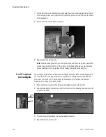
3. Disconnect the wiring harness from the inspiratory valve and safety valve actuators.
4. Remove the four M4 X 12 socket head screw that secure the assembly to the main
manifold and remove the Inspiratory Valve assembly.
5. Install the new Inspiratory Valve assembly to the main manifold using four M4 X 12
socket head screws. Torque = 2.0 Nm
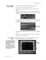
Note: On original main manifold without guide pins use “Safety Valve Alignment
tool” (1505-8598-000) to align the inspiratory Valve Assembly to the main
manifold.)
6. Transfer or install the new Safety Valve Actuator (M1114504 and Seal
(1505-8600-000) to the new Inspiratory Valve Assembly. Apply a small amount
(only enough to wet the surface) of Loctite 271 to screw. Torque = 2.0 Nm
7. Perform Service level tests and calibrations. Refer to section 5.2.3, 5.2.5, 5.2.9,
5.2.10, and 5.2.12.
8. Install Vent Engine assembly into chassis. Refer to section 9.3.2.
9. Install chassis into housing. Refer to section 9.3.1.
10.Perform Super User calibrations per Section 5.1.1.
11.Perform Automated Checkout per Section 3.2.
Safety valve
alignment tool
Summary of Contents for Engstrom Carestation
Page 1: ...Engström Carestation Technical Reference Manual ...
Page 12: ...Engström Carestation x 08 07 1505 1018 000 ...
Page 52: ...Engström Carestation 2 26 08 07 1505 1018 000 ...
Page 100: ...Engström Carestation 5 26 08 07 1505 1018 000 ...
Page 124: ...Engström Carestation 7 16 08 07 1505 1018 000 ...
Page 188: ...Engström Carestation 8 26 08 07 1505 1018 000 ...


