background image

1505-1018-000      08/07     


9-1

9 Repair Procedures

In this section

9.1 Circuit Board Replacement precautions  . . . . . . . . . . . . . . . . . . . . . . . . . . . . . . . . . . . . . . . .9-3

9.1.1 Software download . . . . . . . . . . . . . . . . . . . . . . . . . . . . . . . . . . . . . . . . . . . . . . . . . . .9-3

9.1.2 Required calibrations . . . . . . . . . . . . . . . . . . . . . . . . . . . . . . . . . . . . . . . . . . . . . . . . .9-3

9.2 How to bleed gas pressure from the machine . . . . . . . . . . . . . . . . . . . . . . . . . . . . . . . . . . . .9-4

9.3 Accessing chassis components  . . . . . . . . . . . . . . . . . . . . . . . . . . . . . . . . . . . . . . . . . . . . . . .9-4

9.3.1 To remove the chassis from the housing . . . . . . . . . . . . . . . . . . . . . . . . . . . . . . . . . .9-5

9.3.2 To remove the Vent Engine from the chassis   . . . . . . . . . . . . . . . . . . . . . . . . . . . . . .9-5

9.3.3 To replace chassis mounted components   . . . . . . . . . . . . . . . . . . . . . . . . . . . . . . . .9-6

9.3.4 To replace vent engine components  . . . . . . . . . . . . . . . . . . . . . . . . . . . . . . . . . . . . .9-6

9.3.5 To replace inspiratory valve assembly (1505-8502-000)   . . . . . . . . . . . . . . . . . . .9-9

9.3.6 To replace free breathing valve (0211-1454-100)  . . . . . . . . . . . . . . . . . . . . . . .  9-10

9.3.7 To replace Vent Engine assembly, complete   . . . . . . . . . . . . . . . . . . . . . . . . . . . .  9-11

9.3.8 To replace Vent Engine, sub-assembly  . . . . . . . . . . . . . . . . . . . . . . . . . . . . . . . . .  9-11

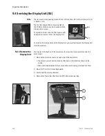
9.4 Servicing the Display Unit (DU)   . . . . . . . . . . . . . . . . . . . . . . . . . . . . . . . . . . . . . . . . . . . . .  9-12

9.4.1 Remove the Display Unit  . . . . . . . . . . . . . . . . . . . . . . . . . . . . . . . . . . . . . . . . . . . .  9-12

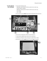
9.4.2 Disassemble the Display Unit  . . . . . . . . . . . . . . . . . . . . . . . . . . . . . . . . . . . . . . . .  9-13

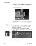
9.4.3 To replace the CPU board   . . . . . . . . . . . . . . . . . . . . . . . . . . . . . . . . . . . . . . . . . . .  9-14

9.4.4 To replace the LCD display . . . . . . . . . . . . . . . . . . . . . . . . . . . . . . . . . . . . . . . . . . .  9-15

9.4.5 To replace the backlights  . . . . . . . . . . . . . . . . . . . . . . . . . . . . . . . . . . . . . . . . . . . .  9-16

9.4.6 To replace the Inverters   . . . . . . . . . . . . . . . . . . . . . . . . . . . . . . . . . . . . . . . . . . . . .  9-17

9.4.7 To replace the front enclosure or components . . . . . . . . . . . . . . . . . . . . . . . . . . .  9-18

9.5 Servicing the High Performance Display Unit (HPDU) . . . . . . . . . . . . . . . . . . . . . . . . . . . .  9-20

9.5.1 Remove the Display Unit. . . . . . . . . . . . . . . . . . . . . . . . . . . . . . . . . . . . . . . . . . . . .  9-20

9.5.2 Disassemble the Display Unit  . . . . . . . . . . . . . . . . . . . . . . . . . . . . . . . . . . . . . . . .  9-21

9.5.3 CPU Fan . . . . . . . . . . . . . . . . . . . . . . . . . . . . . . . . . . . . . . . . . . . . . . . . . . . . . . . . . .  9-21

9.5.4 To replace the CPU board   . . . . . . . . . . . . . . . . . . . . . . . . . . . . . . . . . . . . . . . . . . .  9-22

9.5.5 To replace the LCD display . . . . . . . . . . . . . . . . . . . . . . . . . . . . . . . . . . . . . . . . . . .  9-23

9.5.6 To replace the backlights  . . . . . . . . . . . . . . . . . . . . . . . . . . . . . . . . . . . . . . . . . . . .  9-25

9.5.7 To replace the Inverters   . . . . . . . . . . . . . . . . . . . . . . . . . . . . . . . . . . . . . . . . . . . . .  9-26

9.5.8 To replace the front enclosure or components . . . . . . . . . . . . . . . . . . . . . . . . . . .  9-27

9.6 Adjusting the display arm  . . . . . . . . . . . . . . . . . . . . . . . . . . . . . . . . . . . . . . . . . . . . . . . . . .  9-29

9.6.1 Adjust upper pivot   . . . . . . . . . . . . . . . . . . . . . . . . . . . . . . . . . . . . . . . . . . . . . . . . .  9-29

9.6.2 Adjust lower pivot  . . . . . . . . . . . . . . . . . . . . . . . . . . . . . . . . . . . . . . . . . . . . . . . . . .  9-30

9.6.3 Adjust arm bearing  . . . . . . . . . . . . . . . . . . . . . . . . . . . . . . . . . . . . . . . . . . . . . . . . .  9-30

9.7 Removing a compressor from the cart  . . . . . . . . . . . . . . . . . . . . . . . . . . . . . . . . . . . . . . . .  9-31

9.8 Attaching Labels   . . . . . . . . . . . . . . . . . . . . . . . . . . . . . . . . . . . . . . . . . . . . . . . . . . . . . . . . .  9-32

9.8.1 Key/BID label  . . . . . . . . . . . . . . . . . . . . . . . . . . . . . . . . . . . . . . . . . . . . . . . . . . . . .  9-32

9.8.2 Feature label  . . . . . . . . . . . . . . . . . . . . . . . . . . . . . . . . . . . . . . . . . . . . . . . . . . . . . .  9-32

Summary of Contents for Engstrom Carestation

Page 1: ...Engström Carestation Technical Reference Manual ...

Page 2: ...o oD D D Dy y y yn n n na a a am m m mii i ic c c cs s s s II I In n n nv v v vii i ie e e ew w w w and EVair 03 are registered trademarks of Datex Ohmeda Inc Other brand names or product names used in this manual are trademarks or registered trademarks of their respective holders AAAX11111 AAAXX111111AA The X represents an alpha character indicating the year the product was manufactured H 2004 J ...

Page 3: ...ent is not to be reproduced in any manner nor are the contents to be disclosed to anyone without the express authorization of the product service department Datex Ohmeda Ohmeda Drive PO Box 7550 Madison Wisconsin 53707 2007 Datex Ohmeda Inc Engström Carestation ...

Page 4: ...rred to within or that abnormal or unusual circumstances may not warrant or suggest different or additional procedures or requirements This manual is subject to periodic review update and revision Customers are cautioned to obtain and consult the latest revision before undertaking any service of the equipment Comments and suggestions on this manual are invited from our customers Send your comments...

Page 5: ...ion 1 1 What this manual includes 1 2 1 2 User s Reference manuals 1 2 1 3 Conventions used 1 2 1 4 What is an Engström Carestation 1 3 1 5 Ventilator overview 1 5 1 6 Display controls and indicators 1 7 1 7 Ventilator display 1 8 1 7 1 Using menus 1 10 1 8 Symbols used in the manual or on the equipment 1 11 ...

Page 6: ...tions 2 13 2 3 System Connections 2 14 2 3 1 Display Unit 2 14 2 3 2 High Performance Display Unit 2 15 2 3 3 Communication channels 2 16 2 3 4 Ventilator Control Board VCB 2 18 2 3 5 Ventilator Monitoring Board VMB 2 20 2 3 6 Power Management Board PMB 2 23 2 3 7 Other Electronic Items 2 23 2 3 8 Motherboard backplane 2 24 2 3 9 Monitoring Interface Board Monitoring Module Bays 2 25 3 Checkout Pr...

Page 7: ... 4 17 4 4 8 Resetting feature option key codes 4 18 5 Service Tests and Calibration 5 1 Calibration super user 5 2 5 1 1 Calibration procedure 5 3 5 2 Service level tests and calibration 5 4 5 2 1 Service application setup 5 4 5 2 2 Test setup 5 4 5 2 3 Vent engine debris clean out 5 5 5 2 4 Regulator output pressure test 5 6 5 2 5 Vent engine leak test low pressure 5 8 5 2 6 Vent engine leak test...

Page 8: ...pressure leak and compliance check 7 3 7 1 4 Safety valve relief and back pressure 7 4 7 1 5 Exhalation valve calibration check 7 5 7 1 6 Exhalation flow sensor calibration test 7 5 7 1 7 Measure breathing circuit resistance 7 6 7 1 8 Air inspiratory flow sensor calibration check 7 6 7 1 9 O2 inspiratory flow sensor calibration check 7 6 7 1 10 O2 sensor test and calibration 7 6 7 1 11 Neonatal fl...

Page 9: ...Download 8 10 8 5 EC Service Application PC based 8 12 8 5 1 Port setup 8 12 8 5 2 Main menu and system information 8 12 8 6 VCB Diagnostics and Calibration 8 13 8 6 1 Sensirion sensors 8 13 8 6 2 VCB input signal latch 8 14 8 6 3 VCB channel configurations 8 15 8 6 4 VCB outputs 8 16 8 6 5 Calibrations and tests 8 17 8 6 6 Neon tools 8 18 8 6 7 Peep stability 8 19 8 6 8 Logging checkout results 8...

Page 10: ...lay Unit DU 9 12 9 4 1 Remove the Display Unit 9 12 9 4 2 Disassemble the Display Unit 9 13 9 4 3 To replace the CPU board 9 14 9 4 4 To replace the LCD display 9 15 9 4 5 To replace the backlights 9 16 9 4 6 To replace the Inverters 9 17 9 4 7 To replace the front enclosure or components 9 18 9 5 Servicing the High Performance Display Unit HPDU 9 20 9 5 1 Remove the Display Unit 9 20 9 5 2 Disass...

Page 11: ...External components rear view 10 9 10 6 Display arm mounting hardware 10 10 10 7 Display arm assembly 10 12 10 8 High Performance Display Unit HPDU 10 14 10 9 Display Unit DU 10 16 10 10 Main enclosure external 10 18 10 11 Main enclosure internal 10 20 10 12 Vent Engine 10 22 10 13 Outlet manifold 10 24 10 14 Inlet manifold 10 26 10 15 AC power cords 10 28 10 16 AC Inlet Outlet Components 10 30 10...

Page 12: ...Engström Carestation x 08 07 1505 1018 000 ...

Page 13: ...entilator 1 1 What this manual includes 1 2 1 2 User s Reference manuals 1 2 1 3 Conventions used 1 2 1 4 What is an Engström Carestation 1 3 1 5 Ventilator overview 1 5 1 6 Display controls and indicators 1 7 1 7 Ventilator display 1 8 1 7 1 Using menus 1 10 1 8 Symbols used in the manual or on the equipment 1 11 ...

Page 14: ... and be familiar with the User s Reference manual for this product Refer to the Engström Carestation User s Reference manual if you need further information about the operation of the system 1 3 Conventions used Hard keys Names of the hard keys on the display and modules are written in bold typeface for example Normal Screen Menu selections Menu selections are written in bold italic typeface for e...

Page 15: ...ccessories and options that may not be present or available on all variants This manual does not cover the operation of every accessory refer to the accessory documentation for further information The EC must only be operated by authorized medical personnel well trained in the use of this product for patient ventilation in the intensive care environment It must be operated according to the instruc...

Page 16: ...estation consists of three main components a display a ventilator unit and an optional module bay The display allows the user to interface with the system and control settings The ventilator unit controls electrical power nebulization and pneumatic gas flow to and from the patient The module bay allows the integration of various patient monitoring modules with the ventilator Optional accessories i...

Page 17: ...ilator unit item 6 to Cart item 3 11 Expiratory flow sensor 3 Cart 12 Gas exhaust port 4 Caster 13 Leak test plug 5 Dovetail rails 14 Exhalation valve housing latch 6 Ventilator unit 15 Water trap 7 Display 16 Auxiliary pressure port 8 Nebulizer connection 17 Inspiratory outlet 9 Exhalation valve housing 1 2 3 4 5 6 AB 98 011 8 9 10 11 13 14 15 12 16 17 7 AB 98 127 ...

Page 18: ...unit fan filter 11 Serial communication port Nurse call Port 4 12 Arm holder 13 Port 1 Neonatal Flow Sensor 14 Port 2 Not currently supported 15 Port 3 Used to communicate with PC based Service Application Refer to Section 8 5 16 Communication port Refer to Section 2 3 17 Communication port Refer to Section 2 3 18 Communication port Refer to Section 2 3 19 Communication port Refer to Section 2 3 F...

Page 19: ...atal patient types Push to clear resolved alarms 3 Menu keys Push to show corresponding menu 4 ComWheel Push to select a menu item or confirm a setting Turn clockwise or counterclockwise to scroll menu items or change settings 5 Normal Screen key Push to remove all menus from the screen 6 AC mains indicator The green LED lights continuously when the EC is connected to an AC mains source The intern...

Page 20: ...waveforms are permanently set to Paw and Flow The third waveform may be selected as CO2 O2 Vol Paux or Off 4 General message field Displays informational messages 5 Clock The time may be set in 12 or 24 hour format in the Time and Date menu 6 Patient type icon Displays Neonatal Pediatric or Adult patient type mode 7 Measured value fields Displays current measured values corresponding to the wavefo...

Page 21: ...tion 1505 1018 000 08 07 1 9 When a menu key is selected the waveform fields start at the right edge of the menu The entire waveform is always displayed 1 Menu 2 Waveform fields Figure 1 6 Menu view 1 2 AB 98 014 ...

Page 22: ...u 2 Turn the ComWheel counterclockwise to highlight the next menu item Turn the ComWheel clockwise to highlight the previous menu item 3 Push the ComWheel to enter the adjustment window or a submenu 4 Turn the ComWheel clockwise or counterclockwise to highlight the desired selection 5 Push the ComWheel to confirm the selection 6 Select Normal Screen or push the Normal Screen key to exit the menu a...

Page 23: ...e damage to the equipment Read and follow all warnings and cautions l On power O Off power p On for part of the equipment œ Off for part of the equipment o Standby m Type B protection against electrical shock wW Attention refer to product instructions IEC 60601 1 w Caution ISO 7000 0434 REF Stock number SN Serial number Direct current Alternating current y Earth ground x Protective earth ground Y ...

Page 24: ...ory port Electrical testing certification Inspiratory breath identifier Serial port Module data indicator Module bay port Electronic micropump nebulizer Auxiliary pressure port Display signal input output No battery battery failure Battery in use Bar indicates amount of battery power remaining Silence alarms Submenu Hourmeter Drain outlet ...

Page 25: ... European Council Directive 93 42 EEC for Medical Devices when they are used as specified in their User s Reference Manuals Thexxxxisthecertificationnumber of the Notified Body used by Datex Ohmeda s Quality Systems Date of Manufacture Maximum Neonatal option in installed Functional Residual Capacity option is installed SpiroDynamics option is installed Neonatal patient type Pediatric patient type...

Page 26: ...hat the waste of electrical and electronic equipment must not be disposed as unsorted municipal waste and must be collected separately Please contact an authorized representative of the manufacturer for information concerning the decommissioning of equipment ...

Page 27: ...ay Unit overview 2 12 2 2 2 Software requirements 2 13 2 2 3 DU system connections 2 13 2 3 System Connections 2 14 2 3 1 Display Unit 2 14 2 3 2 High Performance Display Unit 2 15 2 3 3 Communication channels 2 16 2 3 4 Ventilator Control Board VCB 2 18 2 3 5 Ventilator Monitoring Board VMB 2 20 2 3 6 Power Management Board PMB 2 23 2 3 7 Other Electronic Items 2 23 2 3 8 Motherboard backplane 2 ...

Page 28: ...ical grade gasses Additional filtering will not be necessary if supplied gasses are medical grade If gas supply does not meet specifications refer to Appendix A for information regarding risks and recommendations on filters The system includes two separate channels O2 and Air to provide dynamic mixture control of the delivered O2 percentage The Air supply may include an optional compressor unit 1 ...

Page 29: ...ures of supply gas coupling hoses or an occluded filter are identified by the supply pressure transducer Next in the downstream path of flow is a check valve 5 The check valve prevents backflow from the EC that would possibly contaminate the supply pressure lines For example if the O2 supply were to be lost the check valve in the O2 channel will prevent Air from moving back into the O2 supply line...

Page 30: ...s known a conversion of mass flow rate to volumetric flow at ambient conditions can be made using the ambient density of the gas The sensor uses a laminar two channel flow element to split a portion of the flow through the sensor past the heat injection and temperature sensing elements The sensor is pre calibrated and includes an electronic PCB that produces direct digital output of mass flow thro...

Page 31: ...g data from the inspiratory flow sensor a precise volumetric flow versus input current profile is developed that includes both the valve and regulator characteristics A Bleed Resistor 29 is located in parallel with the O2 Flow Control Valve to prevent pressure build up between the O2 regulator and the Flow Control Valve This Bleed Resistor has a 35 ml min nominal flow Air 25 psi 172 kPa 25 psi 172...

Page 32: ...em Using the known mixture composition along with atmospheric pressure and gas temperature information mass flow data from the sensor is converted to delivered volumetric flow towards the patient During calibration the sensor is checked against the output of the O2 and Air flow sensors to ensure proper operation Flow Sensor Flow Sensor Total Flow Inspiratory Effort Valve Free Breathi Check Valv H ...

Page 33: ... Air flows The O2 sensor uses the paramagnetic principle oxygen molecules are attracted in magnetic fields to measure the oxygen concentration The sensor includes two nitrogen filled glass spheres mounted on a suspension containing a conductive coil that is located in a non uniform magnetic field When the system is disturbed by an impulse of current the suspension begins to oscillate inducing an E...

Page 34: ...ly relieve pressure at a nominal 115 cm H2O The inspiratory airway pressure transducer 15 along with its associated zeroing valve is located just prior to the inspiratory outlet port This transducer has a range of 20 to 120 cm H2O and serves as one of three airway pressure measuring devices in the EC O2 Safety Relief Valve Flow Sensor Flow Sensor Total Flow Inspiratory Effort Valve Free Breathing ...

Page 35: ...nciple the transducer is similar to a hot wire anemometer A wire having a large temperature to electrical resistance relationship is placed in the flowstream The wire is kept at a constant temperature using a Wheatstone bridge circuit The current necessary to maintain the resistance of the sensor portion of the bridge is a function of the flow through the sensor At the output of the flow sensor is...

Page 36: ...he other Wheatstone bridge resistors and all associated drive circuitry reside on the VMB As gas Air and Oxygen flows current through the hot wire elements increases These currents are converted to a voltage amplified offset with a voltage reference and converted to a digital value by the 12 bit ADC Because of the bidirectional nature of gas flow at the patient wye a post that is situated between ...

Page 37: ...essure in the auxiliary channel to less than 230 cm H2O 2 1 4 Electronic micropump nebulizer The Aeroneb Professional Nebulizer System Aeroneb Pro by Aerogen Inc 27 is integrated into the EC This nebulizer is electrically connected to the EC and uses proprietary technology to produce a fine droplet low velocity aerosolized drug delivered into the breathing circuit The Aeroneb Pro is designed to op...

Page 38: ...000 or Current Motherboard M1053184 Monitoring Module Power Supply Board M1052831 3 Airway Pressure Transducer boards 1505 5506 000 2 2 1 Display Unit overview The Engström Carestation can use one of two display units the original Display Unit DU or the High Performance Display Unit HPDU The display unit handles most of the machine s user interface functions through the front panel controls and th...

Page 39: ...r A small daughter board DU Interface board provides a communications interface between the DU s CPU and the remainder of the EC system A second daughter board DU Connector board provides hardware connector interfaces for the USB Network ID Ethernet and Display Unit connector ports The CPU board includes a PCMCIA PC Card interface The DU s CPU board provides power and signals for operating the mai...

Page 40: ...ons Display connection 1 1 1 1 DIS connector supports D O Device Interface Solution DIS 2 2 2 2 Network connection Standard Ethernet port for network connectivity 3 3 3 3 Network ID accepts D O proprietary network identification plug 4 4 4 4 USB port standard USB interface for external communication 5 5 5 5 DIS 1 2 3 4 5 AB 98 182 ...

Page 41: ... 07 2 15 2 3 2 High Performance Display Unit The HPDU accommodates the following connections Display connection 1 1 1 1 Future expansion 2 2 2 2 Future expansion 3 3 3 3 Future expansion 4 4 4 4 Future expansion 5 5 5 5 1 2 3 4 5 AB 98 181 ...

Page 42: ...e VMB and receives alarm commands and data 3 A 38 4 Kbaud RS 422 interface relays setting and alarm annunciation information from the VCB and receives sensor data for presentation to the user as well as alarm commands As described later the VMB also communicates directly to the VCB thus there exists a triangle of bi directional communication paths between the DU VCB and VMB An RS 232 Serial port t...

Page 43: ...cessor PSM Future Expansion Neo Flow Sensor Optional PCMCIA 2 RS 422 38 4 Kbaud RS 422 921 6 Kbaud 19 2 Kbaud Future Expansion Service App External I O Serial Nurse Call E M Gas Intel 196 Processor Module Bay ISA Bus RS 232 38 4 Kbaud VMB VCB PMB Display Unit 9 6 Kbaud Serial EV Chassis RS 232 Serial External I O Mod Bus Future Expansion RS 422 38 4 Kbaud RS 232 38 4 Kbaud RS 422 38 4 Kbaud RS 485...

Page 44: ...ential analog signal 12 bits 1000 Hz Auxiliary Pressure sensor via a differential analog signal 12 bits 1000 Hz The VCB contains actuator drive circuits for the following the Air and O2 Flow Valves the Exhalation Valve the Inspiratory Pressure Sensor zeroing valve and the Auxiliary Pressure Sensor purge flow valve The Flow Valve and Exhalation valve actuators are driven using current drive circuit...

Page 45: ...n Port I O 1 Expansion Port I O 2 Air Flow Valve Piezo Electric Neb Board O2 Flow Valve Exhal Valve Aux P Purge Valve 8 MB Flash 1 MB SRAM Exhal Valve Drive w V I Sense RS 232 16 CH MUX 12 Bit ADC 8 UARTS Watchdog V Checks Buzzer Control Safety Valve On Off Exh Valve On Off VMB Sensor Data I O VCB DU Data I O Exh Valve Closed Current Lmt Control Insp Effort Valve Aux P Insp P Expansion Signals Buz...

Page 46: ...ric Pressure onboard VMB 10 bits 11 Hz The VMB controls a safety valve actuator that enables it to unilaterally relieve pressure in the breathing circuit This allows the barotrauma hazard with its 50 ms reaction time to be independently controlled by either action of the VCB or VMB The hazards associated with O2 concentration improper mixture and low exhaled minute volume hypoventilation have much...

Page 47: ...ll not be signalled If an alarm is silenced the nurse call signal will turn off N N N No o o ot t t te e e e Motherboard M1053184 and VMB 1052980 are included in the following kits The 15 pin female D connector configuration Pin 3 relay common Pin 10 normally open Pin 11 normally closed Load current Minimum 100 uA at 100 mVdc Maximum 1 A at 30 Vdc Relay isolated Item Description Stock Number Neona...

Page 48: ...Valve Safety Valve Drive Insp Maneuver Valve Drive ADC MUX Exh Valve Closed UARTS Watchdog V Checks Buzzer Control Exh Valve On Off Safety Valve On Off VMB DU Data I O O2 Sensor Insp Effort Valve Control Exp P Expansion Signals Circuit Power Buzzer Sense Exp P Zero Valve I2C RS 232 Exp Flow Sensor Exp Flow Infc Bd VMB RS 422 38 4 Kb RS 422 921 6 Kb Original VMB Current VMB 505 5501 000 M1052980 AB...

Page 49: ...U for a confirmation signal that shutdown is appropriate unit is not in a ventilation therapy state Once the DU relays this confirmation to the PMB the power off sequence is initiated The PMB supports the operation of the EC chassis fan and the fan on the PMB heatsink 2 3 7 Other Electronic Items The EC employs a separate AC to DC switching power supply for providing a nominal 24v voltage level to...

Page 50: ...o mitigate the risk of an oxygen enriched fire The board features 6 external connectors that exit through a rear sheet metal interface Refer to section 2 3 3 Patient Side Module PSM support connector Neonatal Flow Sensor future expansion Serial future expansion connector Service Application Serial future expansion connector External Serial I O connector Nurse call Main DU connector communication c...

Page 51: ...es circuitry that regulates the raw 16 V power down to 15 V unregulated 15 V regulated and 5 V levels required by the M series monitoring modules RS 422 I O Panel Connectors RS 422 1 12 5V 12 5V Expansion Port I O 2 Expansion Port I O 1 Mod Bus E M Series Module Bay 1 Bay 2 Bay 3 Bay 4 Monitor Interface Board PSM 16V 16V 16V Filtering Filtering Filtering Filtering Filtering 15VD 15V 15V 5V E M Ser...

Page 52: ...Engström Carestation 2 26 08 07 1505 1018 000 ...

Page 53: ...3 4 w w w w WARNINGS After any repair or service of the Engström Ventilator complete all tests in this section Before you do the tests in this section Complete all necessary calibrations and subassembly tests Refer to the individual procedures for a list of necessary calibrations Completely reassemble the system If a test failure occurs make appropriate repairs and test for correct operation ...

Page 54: ...lity report or request technical assistance regarding a checkout failure create and include a Checkout log using the EC Service application Section 8 6 8 Run the Checkout while the EC Service Application is running and select L L L Lo o o og g g g C C C Ca a a all l lii i ib b b br r r ra a a at t t tii i io o o on n n n R R R Re e e es s s su u u ull l lt t t ts s s s When in Standby the Patient ...

Page 55: ...menu select Install Service 23 17 21 On the Install Service menu select Calibration 2 On the Calibration menu select Backlight Test 3 Select Start Test 4 The display will show the test running on light 1 and then on light 2 If the display goes completely blank or flickers during the test one of the lights has failed 3 4 Power failure test 1 Connect the power cord to a wall outlet The mains indicat...

Page 56: ...tion 10 15 Make sure all accessory devices are connected to electrical outlets 1 Connect an approved test device for example UL CSA or AAMI and verify that the leakage current is less than 2 Makesurethattheresistancetogroundislessthan0 2 betweentheequipotential stud and the ground pin on the power cord Voltage Max Leakage Current 120 100 Vac 300 µAmps 220 240 Vac 500 µAmps ...

Page 57: ...ings 4 5 4 2 3 Ventilator Settings 4 7 4 2 4 Parameter Settings 4 7 4 2 5 Defaults 4 8 4 2 6 Factory Defaults 4 10 4 3 Calibration menu 4 11 4 4 Service menu 4 12 4 4 1 Configuration 4 13 4 4 2 Options Key 4 14 4 4 3 Options List 4 14 4 4 4 Options Card 4 14 4 4 5 Copy Configuration 4 15 4 4 6 Service Log menu 4 16 4 4 7 Software Hardware version menu 4 17 4 4 8 Resetting feature option key codes ...

Page 58: ... password supports system configuration and provides access to the Service Log menu Follow the menu structure to access the various service screens On the front panel of the Display Unit press the System Setup key to access the System Setup menu On the System Setup menu select Install Service to access with super user password the Install Service menu select Calibration to access the Calibration m...

Page 59: ...efer to section 4 2 2 Ventilator Settings Configure ventilator settings breath timing flow and modes using backup ventilation Default is Yes Parameter Settings Set volume conditions and CO2 humidity compensation Refer to section 4 2 4 Defaults Set or change default settings Refer to section 4 2 5 Calibration Calibrate airway gas calibrate gas valves and test backlights Refer to section 4 3 Service...

Page 60: ...al trend page Second third fourth fifth Previous Menu Return to previous menu Menu Item Options Page 1 Default Page 2 Default Page 3 Default Page 4 Default Page 5 Default Field 1 Off Select Off to clear trend field rr co2 respiration rate and CO2 Pres Ppeak Pplat Pmean Pmean PEEP Peepe and Peepi MVexp expired minute volume Spont spontaneous MVexp and respiration rate Compl compliance and Raw S S S...

Page 61: ...ime and Date Change clock and calendar functions Previous Menu Return to previous menu Menu Item Message text Values Paw Change color of Paw waveform digits and trend Yellow White Green Red or Blue Flow Change color of Flow waveform Flow and Volume digits and trend Yellow White Green Red or Blue O2 Change color of O2 waveform digits and trend Yellow White Green Red or Blue CO2 Change color of CO2 ...

Page 62: ... kJ d Altitude Change altitude unit m or ft Gas Supply Pressure Change gas supply pressure unit psi kPa or bar Exit Turn power off to exit menu and save settings Menu Item Message text Values Show Alarm Limits Select Yes to show alarm limits in digit fields Yes or No Menu Item Message text Values Hour Set Hour a am p pm Minutes Set Minutes 0 59 Zero seconds Set seconds to zero Day Set Day 1 31 Mon...

Page 63: ... settings or Insp Pause Tpause Timing is available when Flow is set to On On Off Modes with Backup SelectModesthatwillallowbackup ventilation SIMV VC Yes No SIMV PC Yes No Bi Level Yes No CPAP PSV Yes No SIMV PCVG Yes No Previous Menu Menu Item Message text Values TV Based on Change value calculations ATPD no humidifier or BTPS heated humidifier ATPD BTPS CO2 Numbers Changehumiditycompensationtype...

Page 64: ...rent values for the Adult patient type The Current values reflect the settings in the Vent Setup and Alarms Setup menus Any setting that does not have a value shows three dashes Pediatric Show Pediatric facility defaults and settings The Pediatric Settings page contains a list of parameters or settings and the corresponding Saved and Current values for the Pediatric patient type The Current values...

Page 65: ...facility defaults The default selection is No Common values in the saved defaults are overridden if another ventilation mode is set up and saved Factory Reset Save factory settings as facility defaults The default selection is No If Yes is selected Reset machine for defaults to take effect Previous Menu Return to previous menu ...

Page 66: ...00 cmH20 20 mbar 2 kPa 20 hPa 15 mmHg 100 cmH20 20 mbar 2 kPa 20 hPa 15 mmHg 100 cmH20 20 mbar 2 kPa 20 hPa 15 mmHg Insp Pause 0 0 0 Rise Time 100 ms 100 ms 100 ms 100 ms Trig Window 25 25 25 Trigger 2 l min 0 03 l s 1 l min 0 02 l s 0 5 l min 0 008l s 2 l min 0 03 l s Bias Flow 3 l min 0 05 l s 2 l min 0 04 l s 2 l min o 04 l s 3 l min 0 05 l s End Flow 25 25 25 Low FiO2 44 44 44 High FiO2 56 56 ...

Page 67: ...ol Valve calibration Air FCV Start Air Flow Control Valve calibration and leak test Select Start Calibration Open inspiratory port to atmosphere Start Air Flow Control Valve Exhalation Valve Patient must not be connected to circuit during calibration Start Exhalation Valve calibration Connect to the patient circuit Occlude the patient wye Start Exhalation Valve calibration Backlight Test Start dis...

Page 68: ...n the Event log Menu Item Message text Configuration Set language altitude and units Options Key Enable software options Options List Display software options Options Card Install card to enable software options Copy Config Save or install configuration and default settings using memory card Service Log Show error event and alarm histories and system information Exit Turn power off to exit menu ...

Page 69: ...gian Polish Portuguese Russian Spanish Swedish Turkish Default English Paw Change Paw units kPa cmH2O mbar kPa cmH2O or mbar Default cmH2O Flow Change flow units l min or l s l min or l s Default l min CO2 Change CO2 units kPa or mmHg kPa or mmHg Default Height Change height units cm or in cm or in Default cm Weight Change weight units kg or lb kg or lb Default kg Energy Expenditure Change energy ...

Page 70: ...third value of key code Entry 4 Enter fourth value of key code Entry 5 Enter fifth value of key code Entry 6 Enter sixth value of key code Entry 7 Enter seventh value of key code Save New Key Confirm values for key code Control Board ID Control number used by key code Menu Item Message text Available Options FRC SpiroDynamics Neonatal SIMV PCVG BiLevel VG Menu Item Message text Upgrade Yes No Opti...

Page 71: ...nk Fail or OK The field is blank until the data has either been written to the card OK or the system determines it cannot write to the card Fail Saves all settings that are not hardware dependent including facility defaults screen configuration trendsettings colors units decimal marker altitude patient type backup settings and the Show Alarm Limits selection Copy from Card Copy Configuration and d...

Page 72: ... into the service mode options enabled and software installation In the event of a board replacement it is understood that this log like all others could be lost The Event History menu lists the last 200 events logged starting with the most recent The Event History log stores the last 1000 events The Event History log cannot be reset Alarm Log The Alarm Log lists the last 200 alarms since the last...

Page 73: ...l Number ABCDXXXXX Option Package XXX Options Code XXXXXXXXXXXXXXXX VCB Software Version XX XX VCB Hardware Version XXXX XXXX XXX REV A VCB Hardware Serial Number ABCXXXXX DU Software Version XX XX DU Hardware Version XXXX XXXX XXX REV A DU Hardware Serial Number ABCXXXXX VMB Software Version XX XX VMB Hardware Version XXXX XXXX XXX REV A VMB Hardware Serial Number ABCXXXXX PMB Software Version XX...

Page 74: ...o step 11 If the options On do not match the options recorded in step 2 go to the Datex Ohmeda Key Code Generator Web site www docodes com and follow the instructions to request a new Key Code After you receive the new Key Code select Service Menu Options Key Enter the new key code select Save New Key and proceed to step 7 7 Select Service Menu Options key Record the new three digit Control Board ...

Page 75: ...ion setup 5 4 5 2 2 Test setup 5 4 5 2 3 Vent engine debris clean out 5 5 5 2 4 Regulator output pressure test 5 6 5 2 5 Vent engine leak test low pressure 5 8 5 2 6 Vent engine leak test high O2 pressure 5 12 5 2 7 Vent engine leak test high Air pressure 5 14 5 2 8 Calibrate airway pressure transducer Zero and Span 5 16 5 2 9 Verify operation of free breathing valve 5 18 5 2 10 Verify operation o...

Page 76: ...e The menu structure for accessing the calibration software is described in Section 4 Installation and Service Menus Note The Valve calibrations Section 5 1 1 can be performed without performing the Service level test and calibrations Section 5 2 However if the Service level test and calibrations are performed the Valve calibrations should be performed again after the Service level test are comple...

Page 77: ...CV On the Air FCV menu select Start Calibration and allow the system to perform the calibration procedure When Air FCV calibration is complete passed select Previous Menu 5 On the Calibration menu select Exhalation Valve Connect a patient circuit and block the patient port On the Exhalation Valve menu select Start Calibration and allow the system to perform the calibration procedure WhenExhalation...

Page 78: ...on 10 1 1 2 Start the Service Application on the PC Open the VCB and VMB windows 3 To establish communication between the PC Service Application and the EC the EC must be powered On a Read only access is available in normal operation mode b Controlled access is available in Super User or Service modes 5 2 2 Test setup 1 Connect a manual shut off valve to each gas supply inlet Remove the inlet fitt...

Page 79: ...ves 2 Verify that the inspiratory outlet is open to atmosphere not plugged 3 On the VCB screen Verify that the Air and O2 Flow Valves are energized Set the Air DAC counts to 60 000 fully open Set the O2 DAC counts to 60 000 fully open 4 After 20 seconds Close both shut off valves Pulse the Air and O2 flow valves 5 times for 5 seconds Set the Air DAC counts to zero closed Set the O2 DAC counts to z...

Page 80: ... kPa 25 0 10 psi 6 If required adjust the regulator Be sure to tighten the locking nut after adjustment 7 Close the manual Air shut off valve 8 Remove the test gauge and plug the test port O2 regulator 1 Remove the plug from the O2 regulator outlet test port 2 Connect a test pressure gauge to the O2 regulator outlet test port 3 Open the manual O2 shut off valve 4 On the VCB screen Verify that the ...

Page 81: ...0 mm Male Cone Exhalation Valve Exhalation Flow Sensor Pneumatic Resistor Expiratory Zero Valve Expiratory Pressure Inlet Manifold Vent Engine Manifold Outlet Manifold EXP INSP P P H T Paux Air O2 High Pressure Transducer Primary Inlet Check Valv e Check Valv e High Pressure Transducer Primary Inlet P P Inlet Filter Optional Inlet Filter Standard AB 98 196 Paux H Atmosphere EXP INSP Pexp O2 Regula...

Page 82: ...esystemuntilthemeasured ExpiratoryPressure VMB Auxiliary Pressure VCB and Inspiratory Pressure VCB readings indicate 70 cmH2O Note Ensure that the three pressures are stable and approximately equal within 5 cmH2O If not refer to Section 7 2 2 6 Once 70 cmH2O is reached clamp the tube on the low pressure test tool to prevent gas flow from the INSPiratory outlet 7 On the VCB screen select Low P Leak...

Page 83: ...30 mm Male Cone Exhalation Valve Exhalation Flow Sensor Pneumatic Resistor Expiratory Zero Valve Expiratory Pressure Inlet Manifold Vent Engine Manifold Outlet Manifold EXP INSP P P H T Paux Air O2 High Pressure Transducer Primary Inlet Check Valve Check Valve High Pressure Transducer Primary Inlet P P Inlet Filter Optional Inlet Filter Standard AB 98 188 AB 98 101 Paux H Atmosphere EXP INSP Air S...

Page 84: ...ressure in the low pressure sideofthesystemuntilthemeasured ExpiratoryPressure VMB Auxiliary Pressure VCB and Inspiratory Pressure VCB readings indicate 70 cmH2O Note Ensure that the three pressures are stable and approximately equal within 5 cmH2O If not refer to Section 7 2 2 6 Once 70 cmH2O is reached clamp the tube on the low pressure test tool to prevent gas flow from the INSPiratory outlet 7...

Page 85: ...30 mm Male Cone Exhalation Valve Exhalation Flow Sensor Pneumatic Resistor Expiratory Zero Valve Expiratory Pressure Inlet Manifold Vent Engine Manifold Outlet Manifold EXP INSP P P H T Paux Air O2 High Pressure Transducer Primary Inlet Check Valve Check Valve High Pressure Transducer Primary Inlet P P Inlet Filter Optional Inlet Filter Standard AB 98 209 Paux H Atmosphere EXP INSP Air Standard In...

Page 86: ...alation Flow Valve is energized Set the Exhalation DAC counts to 60 000 Verify that the Air Flow Valve is energized Set the Air DAC counts to 60 000 this will release any air pressure in the system De energize the O2 Flow Valve 5 Plug the following ports INSPiratory outlet EXPiratory inlet Auxiliary pressure port Paux 6 Close the manual O2 shut off valve 7 On the VCB screen select High O2 Leak to ...

Page 87: ...30 mm Male Cone Exhalation Valve Exhalation Flow Sensor Pneumatic Resistor Expiratory Zero Valve Expiratory Pressure Inlet Manifold Vent Engine Manifold Outlet Manifold EXP INSP P P H T Paux Air High Pressure Transducer Primary Inlet Check Valve P O2 Check Valve High Pressure Transducer Primary Inlet P Inlet Filter Optional Inlet Filter Standard AB 98 189 Paux H Atmosphere EXP INSP Air Pexp O2 Reg...

Page 88: ...ressure 0 0 psig 4 On the VCB screen Energize the Effort Valve Energized Valve Energize the O2 Flow Valve Set the O2 DAC counts to 60 000 this will release any O2 pressure in the system De energize the Air Flow Valve 5 Plug the INSPiratory outlet 6 Close the manual Air shut off valve 7 On the VCB screen select High Air Leak to start the test 8 After the test is complete Max 6 seconds Verify that t...

Page 89: ...0 mm Male Cone Exhalation Valve Exhalation Flow Sensor Pneumatic Resistor Expiratory Zero Valve Expiratory Pressure Inlet Manifold Vent Engine Manifold Outlet Manifold EXP INSP P P H T Paux O2 Check Valv e High Pressure Transducer Primary Inlet P Inlet Filter Optional Air High Pressure Transducer Primary Inlet Check Valv e P Inlet Filter Standard AB 98 190 Paux H Atmosphere EXP INSP Air Standard I...

Page 90: ... a tee adapter to the INSPiratory outlet Connect a short patient circuit tube from the tee adapter to the EXPiratory inlet Connect a pressure sensing tube from the Inspiratory tee to a manometer and to the Auxiliary pressure port Paux 4 Open the manual Air O2 shut off valve 5 On the VCB screen Verify that the Exhalation Flow Valve is energized Verify that the Air Flow Valve is energized Select Sta...

Page 91: ...e Exhalation Valve Exhalation Flow Sensor Pneumatic Resistor Expiratory Zero Valve Expiratory Pressure Inlet Manifold Vent Engine Manifold Outlet Manifold EXP INSP P P H T Paux Air O2 High Pressure Transducer Primary Inlet Check Valv e Check Valv e High Pressure Transducer Primary Inlet P P Inlet Filter Optional Inlet Filter Standard AB 98 192 To Manometer Paux H Atmosphere EXP INSP Pexp O2 Regula...

Page 92: ...ive pressure squeeze bulb to the INSPiratory outlet 3 Fully depress the bulb a minimum of 10 times 4 On the VCB screen Verify that the measured Inspiratory Pressure is more positive than 3 cmH2O at all times if not troubleshoot the free breathing check valve and the inspiratory effort valve 5 Disconnect the squeeze bulb from the INSPiratory outlet AB 98 091 ...

Page 93: ...0 mm Male Cone Exhalation Valve Exhalation Flow Sensor Pneumatic Resistor Expiratory Zero Valve Expiratory Pressure Inlet Manifold Vent Engine Manifold Outlet Manifold EXP INSP P P H T Paux Air O2 High Pressure Transducer Primary Inlet Check Valv e Check Valv e High Pressure Transducer Primary Inlet P P Inlet Filter Optional Inlet Filter Standard AB 98 193 Paux H Atmosphere EXP INSP Pexp O2 Regula...

Page 94: ...ve are energized Set the Air DAC O2 DAC and the Exhalation DAC counts to 60 000 3 Connect a negative pressure squeeze bulb to the INSPiratory outlet 4 Plug the EXPiratory inlet and the Auxiliary pressure port Paux 5 Fully depress the squeeze bulb The bulb should not fully inflate in less than 5 seconds if not troubleshoot the inspiratory effort valve 6 Disconnect the squeeze bulb from the INSPirat...

Page 95: ... Male Cone Exhalation Valve Exhalation Flow Sensor Pneumatic Resistor Expiratory Zero Valve Expiratory Pressure Inlet Manifold Vent Engine Manifold Outlet Manifold EXP INSP P P H T Paux Air O2 High Pressure Transducer Primary Inlet Check Valv e Check Valv e High Pressure Transducer Primary Inlet P P Inlet Filter Optional Inlet Filter Standard AB 98 194 Paux H Atmosphere EXP INSP Pexp O2 Regulator ...

Page 96: ... shut off valve 3 On the VCB screen Energize the Auxiliary Pressure Purge valve 4 Block the outlet of the tee 5 Verify that the pressure indicated by the manometer not the PC based application is greater than 90 cmH2O but less than 230 cmH2O Caution Do not allow the pressure to build up over 250 cmH2O if not troubleshoot the umbrella relief valve 1505 3267 000 6 Close the manual Air shut off valve...

Page 97: ...piratory Zero Valve Expiratory Pressure Inlet Manifold Vent Engine Manifold Outlet Manifold EXP INSP P P H T Paux Air O2 High Pressure Transducer Primary Inlet Check Valv e Check Valv e High Pressure Transducer Primary Inlet P P Inlet Filter Optional Inlet Filter Standard AB 98 195 To Manometer Paux H Atmosphere EXP INSP Pexp O2 Regulator O2 Test Port O2 Flow Valve O2 Flow Sensor Total Flow Sensor...

Page 98: ...a syringe inject 60 ml of air into the ventilator through the INSPiratory port 4 After the entire volume is delivered verify that the pressure reading on the manometer is greater than 100 and less than 130 cmH2O if not troubleshoot the safety relief valve Note Pressure may spike higher than 130 cmH2O during 60 ml volume delivery if delivered at a rate greater than 4 l min To Manometer AB 98 090 ...

Page 99: ...e Exhalation Valve Exhalation Flow Sensor Pneumatic Resistor Expiratory Zero Valve Expiratory Pressure Inlet Manifold Vent Engine Manifold Outlet Manifold EXP INSP P P H T Paux Air O2 High Pressure Transducer Primary Inlet Check Valv e Check Valv e High Pressure Transducer Primary Inlet P P Inlet Filter Optional Inlet Filter Standard AB 98 191 To Manometer Paux H Atmosphere Air EXP INSP Standard I...

Page 100: ...Engström Carestation 5 26 08 07 1505 1018 000 ...

Page 101: ...6 4 6 2 3 Every sixty 60 months 6 4 6 3 JunAir EVair03 Compressor Maintenance Model OF302 1 5DSA 6 5 6 3 1 Every twelve 12 months 6 5 6 3 2 Every 10 000 hours 6 6 6 4 Cleaning and sterilizing agents 6 7 6 5 Battery capacity test 6 8 w w w w WARNINGS Do not perform testing or maintenance on theEngström Ventilator while it is being used on a patient Possible injury can result Items can be contaminat...

Page 102: ...cure 3 PowersystemOnandaccesstheInstall Servicemenu TRM Section4 2 Change the following as required a Trends Setup TRM Section 4 2 1 Default Trend Graphical Trends b Display Settings TRM Section 4 2 2 Color Units Show Alarm Limits Time and Date c Ventilator Settings TRM Section 4 2 3 Timing and Flow Modes with Backup d Parameter Settings TRM Section 4 2 4 TV Based on CO2 Numbers 4 Access the Servi...

Page 103: ...ion 4 4 6 Review and reset the error and alarm log entries 5 Access the Install Service menus and perform the following as required TRM Section 5 1 1 a Calibration TRM Section 4 3 O2 FCV Air FCV Exhalation Valve Backlight test b Cal Flag Set to Off c Power system Off 6 System Checkout TRM Section 3 a Power system On and verify the Calibration Required message is not displayed upper right portion o...

Page 104: ...and can correct as needed If there is any indication of moisture in the filter the main manifold must be inspected to ensure there are no visual signs of moisture entering into the ventilator engine 7 Complete the battery capacity test Section 6 5 8 Electrical safety tests Section 3 5 9 Complete all Service level tests and calibrations Section 5 2 10 Complete all Super User calibrations Section 5 ...

Page 105: ...place if necessary Part numbers 6243000 and 6242500 refer to JunAir EVair03 TRM Figures 4 and 7 6 Install filter kit f OF302 1 5SDA 5471001 Filter kit includes the following components Intake filters 2 each 5412400 Refer to JunAir EVair03 TRM Figure 5 F 5 um filter 2 each 4071230 Refer to JunAir EVair03 TRM Figures 6b and 6c F 0 01 um Filter 1 each 4071240 Refer to JunAir EVair 03 TRM Figure 6d F ...

Page 106: ...alibrations 1 Install 10 000 Hour Kit after 10 000 hours of operation Check hour meter P N 5471002 10 000 Hour Kit 230V 50 Hz P N 5471003 10 000 Hour Kit 120 V 60 Hz 10 000 Hour Kit includes Motor OF302 Refer to JunAir Evair 03 TRM Page 10 Non return valve 2 each P N 5414500 Refer to the JunAir EVair 03 TRM Figures 4 and 7 Solenoid valve Refer to JunAir EVair03 TRM Figures 8 and 9 Auto drain Refer...

Page 107: ...ted Ethyl Alcohol Sporox II Cidex NU CIDEX CIDEX OPA Autoclaveat 134 C Mild detergent and warm water Expiratory flow sensor yes yes no no no yes yes Exhalation valve housing and parts yes yes no no no yes yes Fan filters no no no no no no yes Aeroneb Pro Nebulizer no no yes yes yes yes yes Water trap cart mounted yes yes no no no yes yes Cables yes no no no no no yes External surfaces no no no no ...

Page 108: ... it does an orderly shutdown 4 Reconnect the power cord to a mains outlet 5 Boot the system with the PCMCIA Service Application for the DU and Compact Flash for HPDU then access the Power Diagnostics function as detailed in Section 8 On the Main Menu of the Service Application select Power Diagnostics On the Power Diagnostic menu select Power Control 6 Page 1 of the Power Controller Power Diagnost...

Page 109: ...stance 7 6 7 1 8 Air inspiratory flow sensor calibration check 7 6 7 1 9 O2 inspiratory flow sensor calibration check 7 6 7 1 10 O2 sensor test and calibration 7 6 7 1 11 Neonatal flow sensor calibration check 7 7 7 2 Troubleshooting Vent Engine Leaks 7 8 7 2 1 Vent engine leak test 7 8 7 2 2 Auxiliary and expiratory pressure circuit leaks 7 12 7 3 Troubleshooting Startup Screen POST messages 7 14...

Page 110: ... 968 counts replace the Zero Valve Replace the Inspiratory Pressure Sensor Board Replace the Vent Control board VCB 2 Expiratory Pressure Sensor Zero Failure With the Expiratory Pressure Zero Valve actuated raw counts from the Expiratory Pressure Sensor must be between 631 and 968 if not test results indicate Fail and Pexp sensor out of range message is displayed Use EC Service Application PC base...

Page 111: ...liance check If there are errors in the calculation negative values divide by zero the results will be dashed The results of this calculation will be displayed after the Safety Relief Valve test is completed 1 The first calculation is compliance and is based on the amount of time it takes for a 3 lpm flow to create 34 cmH2O of pressure at the Pexp sensor If this pressure cannot be achieved a Faile...

Page 112: ...splayed Use the Service Application to simulate this test a If pressure remains significantly above 2 cmH2O Listen for the valve actuator to click when actuating Check the connections to the safety relief valve Ensure seat seal interface is clean Replace the Manifold Assembly b If pressure is only slightly above 2 cmH2O Re zero pressure sensors Ensure seat seal interface is clean If Exhalation Val...

Page 113: ... or the Safety Relief Valve The Pexp value must return to less than 2 within 250 msec If not re zero and repeat or replace the Pexp sensor 3 If only this check is failing a Use the Service Application to verify at least 4 l min is generated by the FCV If not Recalibrate the FCV Replace the FCV b Remove the Exhalation Valve Assembly and ensure the Voice coil shaft is clean and dry and moves freely ...

Page 114: ...e O2 Flow Sensor is functioning and compares the flow and temperature measurements with the total flow sensor at 30 l min Total flow and O2 flow must be within 15 and temperature must be within 9 C Failure can be due to lack of flow as well as flow or temperature differences Use the EC Service Application Section 8 5 to simulate the test and isolate the problem If this check fails all ventilator f...

Page 115: ...the circuit occlusion AfterdetectingthatPawdropsbelow3cmH2O flowwillbesetat20l min The exhalation valve is closed a The Total Flow Sensor must be within 25 of the expiratory neonatal flow absolute value 4 59 l min b The Total Flow Sensor must be within 15 of the inspiratory neonatal flow absolute value Use the EC Service Application to simulate the test and isolate the problem If this check fails ...

Page 116: ... assistance regarding a checkout failure create and include a Checkout log using the EC Service Application 7 2 1 Vent engine leak test While retaining the leak test setup 1 ClosetheAirandO2 flowvalvestolimitthecomponentstested removethe checkmarks from the boxes next to the DAC counts 2 Repeat the Vent Engine Leak Test If the test passes proceed to step 5 If the leak remains toggle the Effort Val...

Page 117: ...ale Cone Exhalation Valve Exhalation Flow Sensor Pneumatic Resistor Expiratory Zero Valve Expiratory Pressure Inlet Manifold Vent Engine Manifold Outlet Manifold EXP INSP P P H T Paux Air O2 High Pressure Transducer Primary Inlet Check Valve Check Valve High Pressure Transducer Primary Inlet P P Inlet Filter Optional Inlet Filter Standard AB 98 186 AB 98 101 Paux H Atmosphere EXP INSP Pexp P P O2 ...

Page 118: ... O2 flow valve by checking the O2 Flow Valve box verify that 60000 DAC counts are set 6 Repeat the Vent Engine Leak Test If the test fails check the individual components in the O2 Flow path If the test passes check the individual components in the Air Flow path ...

Page 119: ...e Flow Valve Regulator Flow Valve Check Valve High Pressure Transducer Inlet Filter Primary Inlet Relief Valve Auxiliary Pressure Purge Valve Test Port Test Port H 30 mm Male Cone Exhalation Valve Exhalation Flow Sensor Pneumatic Resistor Expiratory Zero Valve Expiratory Pressure Inlet Manifold Vent Engine Manifold Outlet Manifold EXP INSP P P P P H T Paux AB 98 111 Paux H Atmosphere Air EXP INSP ...

Page 120: ...g the Exhalation Pressure opening on the front panel Repeat the test a If pressures equal the problem is from the Exhalation valve housing or the seal located between the Exhalation valve and the front panel b If not continue Warning Before removing restrictors shut off supply valves and open flow valves to bleed system pressure build up 1 Remove the restrictor and reinstall the restrictor access ...

Page 121: ...ith new restrictor continue 2 Check seals on the following individual components in the order listed replace components as needed and repeat the test a Restrictor cover gasket b Auxiliary pressure relief valve c Auxiliary pressure zero valve gasket d Auxiliary pressure sensor o ring e Outlet manifold o ring 3 If failure occurs replace the following components in the order listed a Auxiliary pressu...

Page 122: ... detection failed Service is required to correct a faulty connection to the speaker Reconnect the speaker if possible Replace DU CPU board if speaker connection can not be corrected NOTE ECC failed xx The RAM memory ECC circuitry is faulty Replace the DU CPU board NOTE System reset EC xx This usually indicates a software BIOS failure Report this error along with the machine logs to Technical Suppo...

Page 123: ...h card and reload software If problem persists replace the HPDU CPU board ERROR System reset FFFF FF FF Indicates the HPDU lithium battery has lost contact with the holder or the battery is below voltage Replace the lithium battery if below rated voltage Install the software downloader card to restore system setups ERROR watchdog circuit failed This indicates a hardware failure Replace the HPDU CP...

Page 124: ...Engström Carestation 7 16 08 07 1505 1018 000 ...

Page 125: ...he cable connecting the main PCB to the rotary encoder at J38 is properly seated within the mating connector 2 Verify that the revision of the flex cables connecting the main PCB to the keypads at J23 and J26 are at revision 101 or greater by inspecting the labels directly adhered to the flex cables 3 Replace the rotary encoder 4 Replace the HPDU main PCB Unit fails to boot and the green LED is on...

Page 126: ...p Ventilation if in Therapy Cycle power Replace display unit CPU board none Neo Flow Sensor Comparison High Neo TVexp Neo TVinsp 0 3 Neo TVinsp or 5 mL whichever is greater for 6 consecutive breaths Freeze vent engine volume compensation on first breath detection Calibrate neo flow sensor Check neo flow sensor and cable connections Replace neo flow sensor Replace neo flow sensor cable Replace VMB ...

Page 127: ...ace On Standby switch Check replace PMB Air supply pressure high Air Supply Pres High Low Air supply pressure 95 psig for more than 0 5 seconds May result in FiO2 low alarm Check air supply Disconnect sensor and verify output is zero gauge pressure Interchange harness connections on both supply pressure sensors If alarm follows the sensor replace supply pressure sensor If not check replace VMB Air...

Page 128: ...ies disconnected and system temperature stabilized use Service App to check temperatures of air and total flow sensors Air flow sensor and total flow sensor shall not differ by more than 9 C Replace sensors Backup audio failure Backup Buzzer POST Medium Current to buzzer indicates audio is not sounding This alarm is logged at start up and can be de escalated but cannot be cleared from the screen T...

Page 129: ...selected the DU commands the MGAS to start sampling again Check that the sample tube is connected Check that the water trap is connected Check that the gas outlet is not blocked Replace Module Check sample gas out CO2 or O2 waveform instruction Check sample gas out Wait 30 sec and press NormalScreen to continue MGAS Check Sample Gas Out 40 Sec MGAS Check Sample Gas Out 60 Sec Low Medium MGAS commu...

Page 130: ...heat Medium Medium CPU fan speed less than 2500 RPM 50 of nominal speed Temperature reading of either DU thermistor 60 C Verify fan connection Verify fan is not spinning while powered If not then replace fan Replace DU CPU board Exp flow sensor failure Exhalation Flow Sensor Communications Failure High Failedcommunicationswithexhalation flow sensor Use open loop pressure control Check harness conn...

Page 131: ... Insp Flow Sensor Supply Voltage If yes Disconnect vent engine harness at air flow sensor If voltage error stops replace air flow sensor Disconnect vent engine harness at O2 flow sensor If voltage error stops replace O2 flow sensor Disconnect vent engine harness at VCB If voltage error stops replace harness If no Check connection to O2 Flow Sensor Interchange harness connection between O2 and tota...

Page 132: ...eamp EEPROM Error in SSSboard EEPROM Voltage error or Lamp control failure Replace Module Module not compatible Module Not Compatible Low The monitoring module detected is not compatible with system software Refer to Airway Modules Section 5 in the User s Reference manual Remove and reseat Module Check software revision in the Service Log Replace Module Negative airway pressure Negative Pressure H...

Page 133: ...ify FMI 34014 has been completed on unit Calibrate neo flow sensor Check neo flow sensor and cable connections Replace neo flow sensor Replace neo flow sensor cable Replace VMB Repace motherboard Replace VCB No neo flow sensor No Neonatal Flow Sensor Therapy High Both neonatal flow sensor hot wires reporting less than 20 ADC as measured by the VCB or VMB Calibrate neo flow sensor Check neo flow se...

Page 134: ...ace motherboard Replace PMB No battery backup Note in alarm message PMB POST Failure Medium Power controller failed CPU self tests Note question mark at end of message and no battery status indicator on display Cycle power Replace PMB No battery backup Battery Charge Fail or Standby Current High Medium The system is powered on with a battery current 1 3 amps or System is in Standby and the charge ...

Page 135: ...place PMB No battery backup Standby Bulk Charge 12Hrs Medium System is in Standby and the charge modeisbulkchargingandtheduration has exceeded 12 hours RefertoSection8 1 3formore information Check connections Replace batteries Replace PMB No D lite sensor MGAS source D lite off High MGAS Ppeak 3 cmH2O and MGAS Ppeak 5 cmH2O Vent Ppeak for 3 consecutive breaths Verify tube connections at D lite sen...

Page 136: ...ify output is zero gage pressure Interchange harness connections on both supply pressure sensors If alarm follows the sensor replace supply pressure sensor If not check replace harness If not harness check replace VMB O2 supply pressure low Flow Wave Air only O2 Supply Pres Low Medium O2 supply pressure 24 3 psi for more than 0 5 seconds Latched De escalatable Go to 100 Air Check O2 supply Disconn...

Page 137: ...supply input harness and verify output is still out of range Check replace DC power supply input harness If out of range and harness is OK replace DC power supply Measure voltage at F1 both sides on PMB Range is 20 32V Check replace fuse F1 on PMB Replace PMB Pair sensor out of range Air Supply Pressure Sensor Out of Range Low Out of range Air supply pressure sensor data Range is 195 to 4760 mV Ch...

Page 138: ...ressure sensors read 6 3 cmH20 Open circuit and verify pressure is 2 cmH20 Check replace zero valves Replace appropriate pressure sensor board Replace appropriate flow control valve Paux high Paux High Low Paux 100 cmH2O De energize Paux purge valve if purge valve is energized until alarm condition clears VerifyPauxport andanytubingthatisconnectedtoPauxport isnotoccludedwhenpurgevalveisenergized p...

Page 139: ...Pinsp sensor out of range Paw insp Sensor Out of Range High Out of range Paw insp sensor data 50 ms or Inspiratory Pressure Zero Valve energized for 1 second Range 10 4095 mV Check replace harness Interchange Paux and Pinsp connections If Pinsp alarm stops replace Pinsp sensor If Pinsp alarm continues replace VCB Pinsp sensor out of range Paw insp Zeroing Error Low Range for zero pressure 631 968 ...

Page 140: ...n 2 in the special behavior column is active or if condition 1 in the special behavior column is not detected within 15 seconds of the VCB or VMB issuing A high priority alarm All high priority alarms that have the VCB or VMB as the source will activate this alarm Adjust speaker volume to its highest volume If alarm stops replace DU speaker Check DU speaker connection Replace speaker Replace DU CP...

Page 141: ...r and cable connections Replace neo flow sensor Replace neo flow sensor cable Replace VMB Repace motherboard Replace VCB Sample line blocked CO2 or O2 waveform instruction Continuous blockage Check sample line and D fend Wait 30 secondsandpress Normal Screen to continue MGAS Line Blocked 40 Sec MGAS Line Blocked 60 Sec Low Medium MGAS communicates The sample tubing inside or outside the monitor bl...

Page 142: ...B Check replace motherboard Check replace DU system interface PCB connector panel assembly Check replace DU CPU board Failed State message System failure Service required DU to VMB Com Error Failed Proper communications from the DU to the VMB is not successfully completed within 90 seconds after startup or within a 10 second window after communications have been established with the DU Run Backup ...

Page 143: ...ror Failed Proper communications from the VCB to the DU is not successfully completed within a 10 second window Note Timing does not start for 90 seconds after power up Run Backup Ventilation if in Therapy Cycle power Check error log for underlying causes such as voltage range errors Using service card check DU communication to VMB If multiple subsystem communication failures Check replace DU cabl...

Page 144: ...ssembly Check replace DU CPU board If not multiple subsystem communication failures Check replace DU cable Verify VMB is fully inserted into mother board Replace VMB Check replace motherboard Check replace DU system interface PCB connector panel assembly Check replace DU CPU board Failed State message System failure Service required VMB to VCB Com Error Failed Proper communication of the high spee...

Page 145: ...green LED on DU is lit If LED is not lit check AC mains source check rear power cord clamp check fuses IfLEDislit checkoutputofDCpowersupplyatscrewterminals Rangeis20 32V Ifoutofrange disconnect DC power supply input harness and verify output is still out of range Check replace DC power supply input harness If out of range and harness is OK replace DC power supply Measure voltage at F1 both sides ...

Page 146: ... If yes Disconnect harness at flow sensor If voltage error stops replace flow sensor Disconnect vent engine harness at VCB If voltage error stops replace harness If no Check connection to Total Flow Sensor Interchange harness connection between air and total flow sensor If this alarm stops replace total flow sensor If this alarm persists check replace harness If harness is OK replace VCB Alarm mes...

Page 147: ...ng 300 mLpm was measured above 290 mLpm and could not be extrapolated down 1 Verify breathing circuit is connected and not leaking 2 Verify low pressure vent engine system is not leaking 3 Verify exhalation valve is properly connected and all seals are in place 4 Verify gas flow from flow control valves Recal if necessary Aborted Calibration or test in progress has been aborted None Air Flow Senso...

Page 148: ... tube connecting Insp port to Exp port is not occluded kinked Bad O2 Flow Not able to achieve proper flow during exhalation valve calibration Set at 4 L min 1 Verify FCV is opening to give flow Should be at least 2 L min If no flow replace FCV Barometric Chk Barometric pressure sensor check in progress None Barometric Chk Complete Barometric Chk passed None Barometric Chk Fail During Barometric pr...

Page 149: ...essure achieved 1 Verify breathing circuit is connected and not leaking 2 Verify low pressure vent engine system is not leaking 3 Verify exhalation valve is properly connected and all seals are in place 4 Verify gas flow from flow control valves Recal if necessary Can t Pressurize1 Value During 1st half of Low Pressure leak check the breathing circuit could not reach 34 cmH2O Value max exp pressur...

Page 150: ...g Air or O2 flow sensor check air flow sensor temp is more than 9 C different than total flow sensor temp Value temperature difference C 1 If only one flow check fails replace that flow sensor 2 If both Air and O2 flow check fails replace total flow sensor Disagree Tot Value1 Air Value2 During air flow sensor check air flow sensor is more than 15 different than total flow sensor at a nominal flow ...

Page 151: ...upply pressure drops below 30 psi Check for weak or restricted gas pressure supply Failed Supply Press Value During FCV calibration inadequate supply pressure Check gas supply source to see if it is too weak or restricted Failed Supply Press2 Value During FCV calibration inadequate supply pressure Check gas supply source to see if it is too weak or restricted Failed Supply Press3 Value During FCV ...

Page 152: ... only Flow Cal Waiting for Sensiron Total flow sensor is being set up to read the proper gas for the current valve calibration None Flow Diff Value Exhalation flow sensor check Value flow difference between insp total flow sensor and exh flow sensor mL min Must be less than 20 difference Exp flow tot flow 0 20 tot flow Refer to Section 7 1 6 Flow Too High Value During FCV calibration the FCV is le...

Page 153: ...nly Guaranteed Flow Not Achieved Value Could not bring the flow down to the target flow with the minimum flow command Value minimum flow that was achieved mLpm 1 Verify breathing circuit is connected and not leaking 2 Verify low pressure vent engine is not leaking 3 Verify exhalation valve is properly connected and all seals are in place 4 Verify gas flow from flow control valves Recal if necessar...

Page 154: ...ly Low Air Pressure value Air supply pressure 30 psig Verify proper gas supply Low Exp Pressure Value1 Value 2 During exh valve cal the pressure dropped more than 1 25 cmH2O in 4 msec Value1 Current measured pressure cmH2Ox100 Value2 Current calibration point Check for disconnected breathing circuit during calibration Low Max Flow Value FCV Indicator that system will use the degraded wall supply r...

Page 155: ... vent engine is not leaking 3 Verify exhalation valve is properly connected and all seals are in place 4 Verify gas flow from flow control valves Recal if necessary Neo Flow Sensor Cal Neonatal flow sensor calibration in progress None Neo Flow Sensor Cal Fail Neonatal flow sensor calibration failed 1 Verify neonatal flow sensor is properly connected and properly occluded Recalibrate the sensor 2 C...

Page 156: ... sensor zero check failed because the system was unable to achieve 4 Lpm 1 Verify breathing circuit is connected and not leaking 2 Verify low pressure vent engine is not leaking 3 Verify exhalation valve is properly connected and all seals are in place 4 Verify gas flow from flow control valves Recal if necessary Neonatal Zero Failed Expected 0 Flow Neonatal flow sensor zero check failed because t...

Page 157: ...able flow point being tested mLpm Value2 Inspiratory Flow measured by total flow sensor mLpm Value3 Expiratoryflowmeasuredbyexpiratory flow sensor mLpm 1 Verify breathing circuit is connected and not leaking 2 Verify low pressure vent engine is not leaking 3 Verify exhalation valve is properly connected and all seals are in place 4 Verify gas flow from flow control valves Recal if necessary O2 Flu...

Page 158: ...ygen Flow Sensor Check failed because oxygen supply not detected Verify proper gas supply Oxygen Flow Sensor Fail Oxygen Flow Sensor Check failed because system was unable to achieve 30 Lpm during check 1 Verify breathing circuit is connected and not leaking 2 Verify low pressure vent engine is not leaking 3 Verify exhalation valve is properly connected and all seals are in place 4 Verify gas flow...

Page 159: ...uit is connected and not leaking 2 Verify low pressure vent engine is not leaking 3 Verify exhalation valve is properly connected and all seals are in place 4 Verify gas flow from flow control valves Recal if necessary Paracube Sensor Fail 50 50 O2 Paracube O2 sensor check failed to reach 15 Lpm O2 flow for 50 50 cal 1 Verify breathing circuit is connected and not leaking 2 Verify low pressure ven...

Page 160: ...ilure Rising Flow Not Achieved Value Could not achieve minimum flow required fro step in Checkout Value maximum flow that was achieved mLpm 1 Verify breathing circuit is connected and not leaking 2 Verify low pressure vent engine is not leaking 3 Verify exhalation valve is properly connected and all seals are in place 4 Verify gas flow from flow control valves Recal if necessary Sensor Disagree Va...

Page 161: ...tor for oscillation Replace if necessary 2 If only O2 flow sensor check fails replace O2 flow sensor If both Air and O2 flow sensor checks fail replace total flow sensor unbounded Qin Value Intermediate value in low pressure leak check compliance calculation None for information only Upstream Flow Diff Value Difference between flow measured by total flow sensor and inspiratory wire of neonatal flo...

Page 162: ...uring final flow ramp up before first cal points are taken Weak Supply Detected4 Value FCV calibration Indicator that system will use the degraded wall supply routine for FCV calibration None normal operation A weak supply was detected during final flow ramp up before first cal points are taken if DAC output reached 65 000 counts before flow reached 170 L min Xducer Error Value During Paw Xducer c...

Page 163: ...nload 8 10 8 5 EC Service Application PC based 8 12 8 5 1 Port setup 8 12 8 5 2 Main menu and system information 8 12 8 6 VCB Diagnostics and Calibration 8 13 8 6 1 Sensirion sensors 8 13 8 6 2 VCB input signal latch 8 14 8 6 3 VCB channel configurations 8 15 8 6 4 VCB outputs 8 16 8 6 5 Calibrations and tests 8 17 8 6 6 Neon tools 8 18 8 6 7 Peep stability 8 19 8 6 8 Logging checkout results 8 20...

Page 164: ...ections Note You can not return to the Diagnostic section of the service application after entering the software download section You must reboot the system to exit Software Download The System Information page appears on the right hand side of the screen and displays the following system information System Information Main Menu Remarks Power Diagnostics Access to the Power Supply Diagnostics func...

Page 165: ...s up the following menu selections in the left hand frame and the instructions in the right hand frame Main Menu Power Diagnostics Display Diagnostics Special Functions Software Download Power Diagnostics Power Diagnostics Instructions Power Control Select a menu item to see the power status and measured voltages To troubleshoot a power problem start with the power controller and work forward Prob...

Page 166: ...ower Control Display Unit Main Menu Label Value Format Units Normal range AC Status OK Fail 12Vdc Supply XX XX Vdc 11 70 to 12 30 3 3Vdc Supply X XXX Vdc 3 201 to 3 399 1 5 Vdc Supply X XXX Vdc 1 45 to 1 55 Battery Connected Yes No Battery Status Fail Bulk Chg Over Chg Float Chg Trickle Chg Discharge Battery Current X XXX A Battery 1 Volts XX X 6 0 FAIL red 10 T Chg yellow 10 15 5 Green Vdc 10 0 t...

Page 167: ... 7V typical low fan speed 20 7V typical Vdc 17 5 to 25 0 Fan 1 Status Fail OK Fan 2 Status Fail OK Battery Status Description Fail Battery is disconnected from Power Control Power Diagnostics and is in Trickle mode for 12 hours Bulk Chg Initial phase of battery charging Battery is at 600 mA when system is running and 1 2 Amps when system is in standby Over Chg Topping off remaining 5 10 of battery...

Page 168: ...gnostics page Display Unit Power Diagnostics Power Diagnostics Power Control Display Unit Main Menu Label Value Format Units Normal range 5 0Vdc PCMCIA X XX Vdc 4 50 to 5 50 3 3Vdc PCMCIA X XX Vdc 2 97 to 3 63 5 0Vdc Fan X XX Vdc 4 50 to 5 50 5 0Vdc USB X XX Vdc 4 50 to 5 50 8 0Vdc DIS X XX Vdc 7 20 to 8 80 11Vdc LCD XX XX Vdc 10 35 to 13 62 ...

Page 169: ...t 2 Test Keys Main Menu Display Diagnostics Action when selected Test LEDs Selecting Test LEDs causes the red and yellow LEDS next to the Silence Alarms key to flash for 10 seconds Test Speaker Selecting Test Speaker causes the speaker to sound for 5 seconds Test Backlight 1 Selecting Test Backlight 1 turns backlight 2 off for 10 seconds If screen goes black during test a backlight is out Test Bac...

Page 170: ...d to the card no apparent activity 3 Restart the system with the Service Application to view the logs Revision and PC Card Install Logs Whenever a Software Download is completed the specific software download is recorded in the Revision Log that resides on the system Display Unit and in the PC Card Install Log that resides on the PC Card Compatibility Table The Compatibility Table lists the curren...

Page 171: ...after download on day date time SvcApp Ver XX XX Machine Serial Number ABCDXXXXX Card XXXXXXX System Version XX XX EV FPC Software Level File Name Front Panel Cn EV PMB Stock Number RevX Software Level File Name Serial Power Monitor EV VCB Software Level File Name XXXXXX Vent Control B EV VMB Stock Number RevX Software Level File Name Serial Vent Monitor B EV DUA Stock Number RevX Software Level F...

Page 172: ...wnload ENTERING SOFTWARE DOWNLOAD MODE To return to Diagnostics turn On Standby switch to Standby and turn off AC mains switch in rear Wait 20 seconds then turn on power with the AC mains switch and the On Standby switch Press ComWheel to continue with Download Software Download Remarks Download New Downloads only new software versions not found on the system and compatible with installed subsyste...

Page 173: ...re download power down the system wait for 20 seconds and restart system Download complete When all the required subsystem software is downloaded the following message appears on the screen You must shut down the system to exit the download function Note After powering down the system be sure to wait at least 20 seconds before restarting the system If there is no Front Panel Control software insta...

Page 174: ... Application is running 8 5 2 Main menu and system information The Main Menu appears on the screen and includes the following selections as shown in the table below The main menu includes a Connection Status message area that shows whether or not the program is communicating with the EC The VCB and VMB Diagnostics pages can both be displayed at the same time Closing the main menu closes the applic...

Page 175: ...ibration on the Main Menu brings up the following page that contains five grouped area 8 6 1 Sensirion sensors The Sensirion Inspiratory Flow Sensors group shows the temperature and the flow through each flow sensor Total flow Oxygen and Air Item Total Oxygen Air Temperature XXX X C XXX X C XXX X C Flow ml min XXXXXX XXXXXX XXXXXX ...

Page 176: ...ressure zero valve off Aux Press Purge Valve ON Auxiliary pressure purge valve on OFF Auxiliary pressure purge valve off Exhalation Vlv Open YES VMB is commanding the exhalation valve open NO The valve is not opened VMB Buzzer On YES VMB is activating the buzzer NO Buzzer is not active or is activated by the VCB Nebulizer Detected YES Nebulizer is connected NO Nebulizer is not connected Buzzer Det...

Page 177: ...t XXX X mA 0 to 198 Nebulizer Power Nebulizer power when on Nebulizer power when off XXXXX XXX mV mV On 11500 to 12710 Off 0 to 500 Ambient Temp Ambient temperature near the valve drive circuits XXX X C 0 to 55 Module Power 16 V Circuit breaker for module power XXXXX mV 15200 to 16800 12 5V Supply 12 5 V Supply Voltage XXXXX mV 12040 to 13330 5V Analog 5V analog supply voltage XXXXX mV 4800 to 520...

Page 178: ...nsp Press Zero Inspiratory pressure zero valve on off Not checked Aux Press Purge Auxiliary pressure purge valve on off Not checked Buzzer On Controls the buzzer On Off from the VCB Not checked Air Flow Valve Enables Disables Air flow valve Disabled while a calibration is running Checked Air DAC Set any DAC value from decimal 0 to 65535 for the Air Flow Valve 0 O2 Flow Valve Enables Disables O2 fl...

Page 179: ...tory pressure sensors Exh Flow Exhalation flow sensor zero O2 Sensor Runs the Paracube O2 sensor test Valve Sweep Runs the Valve Sweep calibration Low P Leak Runs Low Pressure Leak Test High O2 Leak Runs High O2 Pressure Leak Test O2 Leak w o filter Displays the calculated vent engine high pressure O2 leak without a filter O2 leak w filter Displays the calculated vent engine high pressure O2 leak ...

Page 180: ...lated from the counts reported by the Neonatal Flow Sensor and the current zero point Inspiratory flow is displayed as positive net flow and expiratory flow is displayed as negative net flow mL min Item Function Unit Insp Flow Displays the Inspiratory Flow counts reported by the Neonatal Flow Sensor Counts Exp Flow Displays the Expiratory Flow counts reported by the Neonatal Flow Sensor Counts Net...

Page 181: ...e Neonatal Flow Sensor Item Function Unit Insp Offset DAC Counts Displays the inspiratory DAC zero offset movement from the last recorded static zero Updated by the dynamic zeroing Counts Exp Offset DAC Counts Displays the expiratory DAC zero offset movement from the last recorded static zero Updated by the dynamic zeroing Counts Insp Offset ADC Counts Displays the calculated inspiratory zero offs...

Page 182: ...exist a message window displays Select Yes to create a Log File 3 Verify the file address location displayed in the Log Calibration results to file area and select Start Logging The Status Log window displays and indicates that the log has been initialized 4 From the EC Ventilator access the Patient Setup menu and select Checkout Follow the screen instructions and select Start Checkout Information...

Page 183: ... log If a Log File does not exist a message window displays Select Yes to create a Log File 5 Verify the file address location displayed in the Log Calibration results to file area and select Start Logging The Status Log window displays and indicates that the log has been initialized 6 From the EC Ventilator access the Calibrations menu from the Install Service menu Select each calibration and fol...

Page 184: ...Engström Carestation 8 22 08 07 1505 1018 000 8 7 VMB Diagnostics Selecting VMB Diagnostics on the Main menu brings up the following page that contains five grouped areas ...

Page 185: ... to 1182 0 O2 Supp Press O2 supply pressure sensor measurement XXX XX psig 9 1 to 127 8 Air Supp Press Air supply pressure sensor measurement XXX X psig 9 1 to 127 8 Reference 1 22V Reference XXXXX mV 1104 to 1338 12 5V Supply 12 5V Power supply to the VMB XXXXX mV 10900 to 13320 6 1V Expiratory 6 1V power supply to the expiratory flow sensor XXXXX mV 5770 to 6370 5V O2 Supply 5V power supply to t...

Page 186: ...ed Not checked Safe Valve Energized Opens closes the safety valve from the VMB energized when checked Not checked O2 Sensor Off Turn oxygen sensor On not checked or Off checked Not checked Exh Flow Sensor Pwr Turn exhalation sensor On checked or Off not checked Checked VMB Buzzer On The VMB turns the buzzer On Off Not checked VMB Reset Resets the VMB disables the watchdog when checked Not checked ...

Page 187: ...pressure transducer Baro P Cal Starts the barometric pressure transducer calibration The calibration will Fail if nothing is entered in the Enter Pressure box Status Displays the results of the barometric calibration Passed or Failed Item Description SW Ver Software version of the acutronic Sensor software Exp Zero ADC Displays the Analog to Digital Counter zero value fro the expiratory flow senso...

Page 188: ...Engström Carestation 8 26 08 07 1505 1018 000 ...

Page 189: ... Unit DU 9 12 9 4 1 Remove the Display Unit 9 12 9 4 2 Disassemble the Display Unit 9 13 9 4 3 To replace the CPU board 9 14 9 4 4 To replace the LCD display 9 15 9 4 5 To replace the backlights 9 16 9 4 6 To replace the Inverters 9 17 9 4 7 To replace the front enclosure or components 9 18 9 5 Servicing the High Performance Display Unit HPDU 9 20 9 5 1 Remove the Display Unit 9 20 9 5 2 Disassemb...

Page 190: ...internal components w When servicing the EC extreme care must be taken to avoid introducing foreign debris into the pneumatic flow passages of the ventilator This includes dust and contaminants on the vent engine and particularly metal chips generated by screw threads Before removing components on the vent engine secure a clean work area and thoroughly clean the vent engine to remove any contamina...

Page 191: ...tem software Caution Do not replace more than one of these boards at a time without first powering up the unit Wait until the initial checkout menu appears to insure that the machine specific information has been replicated 9 1 1 Software download After replacing any of the following boards download the current software for the newly installed subsystem refer to Section 8 4 Display Unit CPU board ...

Page 192: ... related Vent Engine components are mounted on a manifold that occupies the lower tier of the chassis To access the pneumatic components the entire manifold assembly can be removed from the chassis The electrical and related circuit board components occupy the upper tier Electrical components on the Vent Engine connect to the Ventilator Control Board VCB and the Ventilator Monitor Board VMB throug...

Page 193: ...an not be removed with the Exhalation Valve in place 4 Disconnect the Display Cable from the chassis connector 5 Loosen the four captured mounting screws at each corner of the back panel 6 Slide the chassis out of the housing 9 3 2 To remove the Vent Engine from the chassis 1 Remove the circuit board retainer 2 Disconnect the engine harness connectors from the circuit boards 3 Remove the four scre...

Page 194: ...ecure a clean work area and thoroughly clean the vent engine to remove any contaminants Failure to do so may result in damage to the internal components All mounting hardware for Vent Engine components can be accessed from the top When replacing a component ensure that the o ring or gasket under the component is properly seated in the manifold To remove the harness connector from the O2 Sensor rel...

Page 195: ...installed place it on the side or back on a clean surface to protect the mating surface 6 Using an alcohol prep pad damp wipe clean the manifold surface by starting at the opening and wiping away from it This will reduce the risk of loose material dropping into the manifold 7 Carefully inspect the opening in the manifold If there is any visual sign of contamination or discoloration the manifold an...

Page 196: ...the following torque spec chart to properly mount the component Regulator 2 Nm Flow Control Valve 4 Nm O2 Sensor 2 Nm O2 sensor to plate 0 5 Nm O2 sensor plate to manifold 2 Nm Flow Transducer 2 Nm Inspiratory Valve Assembly Manifold 4 Nm Inlet Manifold Sub assembly 4 Nm Outlet Manifold Sub assembly 4 Nm Pneumatic restrictor 1 Nm Pneumatic Restrictor Plate 2 Nm Legris Fitting 4MM 4 nm Zeroing Valv...

Page 197: ...crews Torque 2 0 Nm Note On original main manifold without guide pins use Safety Valve Alignment tool 1505 8598 000 to align the inspiratory Valve Assembly to the main manifold 6 Transfer or install the new Safety Valve Actuator M1114504 and Seal 1505 8600 000 to the new Inspiratory Valve Assembly Apply a small amount only enough to wet the surface of Loctite 271 to screw Torque 2 0 Nm 7 Perform S...

Page 198: ...apper through the hole in the Free Breathing Valve seat and cut off tip of flapper to approximately 7mm 7 Apply a thin film of Krytox to o ring only enough to wet the surface of the o ring and fit o ring into the groove located on the Free Breathing Valve seat 8 Install the Free Breathing Valve seat into the main manifold and tighten valve until it is flush with the manifold 9 Perform Service leve...

Page 199: ...e Vent Engine assembly from the chassis Refer to Section 9 3 2 3 Remove the following components from the Vent Engine assembly a Harness vent engine to VCB VMB 1505 5706 000 b Inspiratory Manifold Panel Assembly with safety valve 1505 8502 000 c Outlet Manifold Panel Assembly including all mounted components 1505 8505 000 d O2 Pipeline Adapter from inlet manifold 1505 3206 000 e AIR Pipeline adapt...

Page 200: ...vice other components of the Display Unit you must first remove the Display Unit from the machine 9 4 1 Remove the Display Unit The Display Unit attaches to the pivot arm with screws that are accessible under the pivot covers 1 Remove the pivot arm covers on each side of the upper pivot The pivot covers are held in place by three tabs in the locations shown by the arrows Slide a thin blade between...

Page 201: ...llowing items The item numbers refer to the parts list in Section 10 9 the fan 26 the connector panel assembly 21 the encoder assembly 12 the battery 5 the speaker 20 To access the mounting screws for the speaker you must first remove the ten screws that hold the mounting plate to the front enclosure so that you can raise the bottom edge of the assembly slightly Refer to section 9 4 4 the rear enc...

Page 202: ... E Fan cable F LCD cable G 3 Remove the remaining four screws H that hold the CPU board to the mounting plate 4 Remove the CPU board from the mounting plate 5 If you are replacing the PCMCIA frame 3 on an existing CPU board remove four screws on back of CPU board you must also apply new gaskets 4 to the frame Align the ends of the gaskets with the top edge of the frame 6 Transfer the battery 5 to ...

Page 203: ...at ZIF zero insertion force connector C Fan cable D LCD cable E 2 Remove the ten screws circled that hold the mounting plate to the front enclosure 3 Remove the mounting plate assembly from the front enclosure 4 Disconnect the backlight harnesses F from the inverter boards 5 Slide the grommet G out of the mounting plate slot transfer to new LCD 6 Remove the four screws circled that hold the LCD to...

Page 204: ...grommet faces toward the inside of the keyhole 9 4 5 To replace the backlights The backlight replacement kit includes a backlight assembly with two backlights and two inverters with mounting hardware To replace the backlight assembly follow the procedure in Section 9 3 to gain access to the assembly To replace the inverters follow the procedure in the next section 1 Remove the one screw J that hol...

Page 205: ... a heatsink Follow the procedure in Section 9 4 4 to gain access to the inverters Replace one inverter at a time 1 Disconnect the backlight cable A from the inverter 2 Remove the two Nylon screws B that hold the inverter to the backplate 3 Slide the inverter out of the sleeve and disconnect it from the CPU harness C 4 Reassemble in reverse order The front inverter The rear inverter A B C A B C ...

Page 206: ...n on one corner of the window to free it from the enclosure 3 Work your way around the window until you can get a hold of it from the back 4 Slowly pry the window from the enclosure 5 Place the front enclosure face down on a flat surface taking care not to damage the encoder 6 Remove any remaining residue from the mounting area clean with isopropyl alcohol 7 Remove the inside protective material f...

Page 207: ... folded over under the membrane 6 Carefullylowerthemembranestraightdowntotheenclosure Seatthemembranein place 7 Remove the backing from the keypad and install it over the membrane switches 8 Attach the ground strap to the enclosure To install the EMI gasket To fully seal the Display Unit enclosure you will need approximately 2 3 meters of EMC gasket 10 Cut the gasket into five strips shown below G...

Page 208: ... the Display Unit To service other components of the Display Unit you must first remove the Display Unit from the machine 9 5 1 Remove the Display Unit The Display Unit attaches to the pivot arm with screws that are accessible under the pivot covers 1 Remove the pivot arm covers on each side of the upper pivot The pivot covers are held in place by three tabs in the locations shown by the arrows Sl...

Page 209: ...r you must first remove the ten screws that hold the mounting plate to the front enclosure so that you can raise the bottom edge of the assembly slightly Refer to section 9 5 5 the rear enclosure 1 You can transfer the captive screws to the new enclosure However the gasket 2 is held in place with adhesive When replacing the rear enclosure also include a new gasket To replace the remaining items re...

Page 210: ...switch flex cable at ZIF zero insertion force connector E Fan cable F LCD cable G Make sure cable is plugged in securely if not screen may display incorrectly white Left membrane switch flex cable at ZIF zero insertion force connector H 3 Remove the remaining four screws I that hold the CPU board to the mounting plate 4 Remove the CPU board from the mounting plate 5 Transfer the battery 5 to the n...

Page 211: ... cable at ZIF zero insertion force connector C Fan cable D LCD cable E Left membrane switch flex cable at ZIF zero insertion force connector F 2 Remove the ten screws circled that hold the mounting plate to the front enclosure 3 Remove the mounting plate assembly from the front enclosure 4 Disconnect the backlight harnesses G from the inverter boards 5 Slide the grommet H out of the mounting plate...

Page 212: ...lay ribbon cable I to the top side of the plate Flip the LCD over to the left of the assembly 8 Disconnect the display ribbon cable J 9 Reassemble in reverse order Note WhenreplacingtheLCD pulltheexcessribboncabletothebottomsideofthe plate as you lower the LCD on to the plate For the backlight harness grommet H ensure that the slit in the grommet faces toward the inside of the keyhole G H J LCD Di...

Page 213: ...assembly To replace the inverters follow the procedure in the next section 1 Remove the one screw K that holds the backlight assembly to the LCD 2 Slide the backlight assembly to the left to free it from the retaining tabs and then lift it out of the holder 3 Transfer the grommet H to the new backlight assembly 4 Reassemble in reverse order Note When replacing a backlight or a backlight inverter y...

Page 214: ... inverters Replace one inverter at a time 1 Disconnect the backlight cable A from the inverter 2 Remove the two Nylon screws B that hold the inverter to the backplate 3 Slide the inverter out of the sleeve and disconnect it from the CPU harness C 4 Reassemble in reverse order The front inverter The rear inverter Note When replacing a backlight or a backlight inverter you must replace both inverter...

Page 215: ...ce 2 Press down on one corner of the window to free it from the enclosure 3 Work your way around the window until you can get a hold of it from the back 4 Slowly pry the window from the enclosure 5 Place the front enclosure face down on a flat surface taking care not to damage the encoder 6 Remove any remaining residue from the mounting area clean with isopropyl alcohol 7 Remove the inside protect...

Page 216: ...lded over under the membrane 6 Carefullylowerthemembranestraightdowntotheenclosure Seatthemembranein place 7 Remove the backing from the keypad and install it over the membrane switches 8 Attach the ground strap to the enclosure To install the EMI gasket To fully seal the Display Unit enclosure you will need approximately 2 3 meters of EMC gasket 10 Cut the gasket into five strips shown below Grou...

Page 217: ...r hardware remove the pivot arm covers on each side of the pivot The pivot covers are held in place by three tabs in the locations shown by the arrows Slide a thin blade between the cover and the pivot housing to release each tab To access the adjustment screw for the arm mount bearing remove the display arm cover 9 6 1 Adjust upper pivot 1 Position the DU as shown Arm vertical DU horizontal 2 Rel...

Page 218: ... top of the DU The DU should remain in place 4 Verify that the DU can be raised and lowered without excessive force 5 Adjust the lower pivot as necessary 9 6 3 Adjust arm bearing 1 Position the DU as shown above Arm forward Upper and lower pivots in line horizontally DU vertical 2 Move the DU side to side Verify that the DU can be moved withoutexcessiveforceandthatit remains in place with slight s...

Page 219: ...WARNING To avoid personal injury two people are required to remove and install the compressor 1 Remove the trim pieces from the side extrusions 2 Remove the compressor mounting hardware from each side of the cart 3 Screw in a lifting handle service tool 5370055 into each side of the compressor 4 Withapersononeachsideofthecart liftthecompressorslightlyandslideitforward out of the cart w CAUTION To ...

Page 220: ...l Use the feature label to attach FRC SpiroDynamics or Neonatal 1 Affix the Feature Label holder to the front of the machine as shown Align the right edge of the label approximately 6 mm from the right edge of the outlet manifold Align the bottom edge of the label approximately 15 mm from the top edge of the outlet manifold 2 Affix the Feature Specific label in the square recesses in the label hol...

Page 221: ...ront view 10 8 10 5 External components rear view 10 9 10 6 Display arm mounting hardware 10 10 10 7 Display arm assembly 10 12 10 8 High Performance Display Unit HPDU 10 14 10 9 Display Unit DU 10 16 10 10 Main enclosure external 10 18 10 11 Main enclosure internal 10 20 10 12 Vent Engine 10 22 10 13 Outlet manifold 10 24 10 14 Inlet manifold 10 26 10 15 AC power cords 10 28 10 16 AC Inlet Outlet...

Page 222: ... 4 X on Compact Flash card HPDU Note For High Performance Display Unit HPDU M1079267 3 Compact Flash Adapter PCMCIA carrier Note For Standard Display Unit only DU 1009 5874 000 4 Windows based EC Service Application 1505 8001 000 5 Cable USB Converter to EC 1505 8587 000 6 Converter USB to RS 422 RS 485 includes USB cable 1505 8586 000 Male pin end 9 pin DSUB Female pin end 9 pin DSUB Port 3 9 pin...

Page 223: ... Nipple 1 8 NPTM 1 5 L Air 0213 5025 335 0213 5026 500 1e Filter body M18 O2 1e Filter body M16 Air 1001 5921 000 1001 5923 000 1a 1b 1c 1d 1e 1 Item Description Stock Number 1 Cable Remote Display Unit 2 meters For connect DU to EC chassis when disassembled for repair and evaluation Refer to section 9 3 M1063496 2 Tool Nebulizer connector Refer to section 10 13 1505 8506 000 3 Safety Valve alignm...

Page 224: ...e 60 cc 1505 3061 000 2 Clamp tubing 7000 0000 097 3 Tee 1 8 inch barb 7000 0000 186 4 Negative low pressure leak test device 0309 1319 800 5 Tee sensing 22 mm to 15 mm 0212 0763 100 6 Connector Endo tube 0219 5060 530 7 Plug 4 mm 1006 3530 000 8 Plug stopper 2 2900 0001 000 9 Silicone tubing 3 16 ID 1006 3666 000 10 Tubing clear 0 125 ID 1605 1001 000 4 6 5 9 7 10 ...

Page 225: ...ERROR undefined OFFENDING COMMAND STACK ...

Reviews: