


DT9100 B
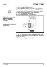
5.2. Connecting the synchronising input
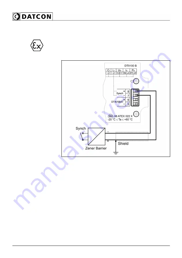
A DT9100 B synchronising input is a digital input for driving
it either with a contact or with a solid state switch. You may
connect an instrument to the input if its output is in
conformity with the following input parameters:
Uo < 30 V, Io < 200 mA, Po < 0.75 W.
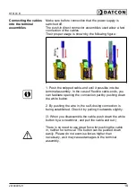
The following figure shows the connection:
Wiring plan, connecting
the synchrinising input
(see also “Application
example”)
Be careful with the polarity
of the cables
1. Push the cable end into the terminal assembly as far as
possible. By pushing the wire in, the self-closing connection
is being established.
2. Check it by pulling it outwards slightly.
20
20180905-V120180905-V1
Summary of Contents for DT9100 B
Page 1: ...DT9100 B Intrinsically Safe Digital Clock Operating Instructions...
Page 47: ...DT9100 B 10 2 Application example 20180905 V1 47...
Page 56: ...DT9100 B 10 8 ATEX Certification 56 20180905 V120180905...
Page 57: ...DT9100 B 20180905 V1 57...
Page 58: ...DT9100 B 58 20180905 V120180905...
Page 59: ...DT9100 B 20180905 V1 59...
Page 60: ...DT9100 B 60 20180905 V120180905...
Page 61: ...DT9100 B 20180905 V1 61...
Page 62: ...DT9100 B 62 20180905 V120180905...
Page 63: ......