DT9100 B
The DT9100 B has a very powerful EMC protection, so
grounding and practice on both sides are generally
unnecessary, but when a particularly high electrical
disturbance device (such as an inverter drive system) is
used nearby, it may be necessary to use the above. An
important rule is that the signal cables, separate from the
power cable.
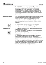
Number of cables
It is recommended to trace the synchronizing contact with a
separate shielded cable and digital outputs on another
cable. To reduce electromagnetic disturbance to the
device, it is imperative to install the wiring shown on the
previous pages and to form the shields as shown in the
diagram.
A common cable can only be used, if the insulation
strength between the wires is 500 V or higher!
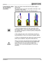
Cables entries
1. Check the conformity of the cables as described in the
Cables Selection section.
2. Prepare the cable for connection. The uninsulated wire
end length should be 8 mm.
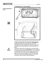
3. Remove the front cover of the device as described in
chapter 4.3.
4. Loosen the clamp nut on the cable gland so that the
cable can be easily inserted. (Do not wrap it down
completely, as it may be lost and the sealing ring may be
lost.)
5. Route the cable through the cable gland into the housing
so long that it can easily loosen the cable tie. (The excess
length can be retracted at the end of the operation.) Make
sure the cable does not damage the device.
18
20180905-V120180905-V1
Summary of Contents for DT9100 B
Page 1: ...DT9100 B Intrinsically Safe Digital Clock Operating Instructions...
Page 47: ...DT9100 B 10 2 Application example 20180905 V1 47...
Page 56: ...DT9100 B 10 8 ATEX Certification 56 20180905 V120180905...
Page 57: ...DT9100 B 20180905 V1 57...
Page 58: ...DT9100 B 58 20180905 V120180905...
Page 59: ...DT9100 B 20180905 V1 59...
Page 60: ...DT9100 B 60 20180905 V120180905...
Page 61: ...DT9100 B 20180905 V1 61...
Page 62: ...DT9100 B 62 20180905 V120180905...
Page 63: ......

