


2-20
Magellan
TM
8500Xt Scanner
Operational Verification
Follow these steps to ensure that your unit has arrived undamaged and is
fully functional before installing it in the counter and connecting it to
your POS system.
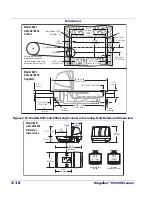
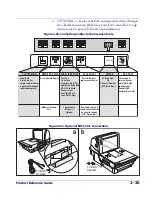
1. If the unit is a scanning-scale, connect the Remote Scale Display
to the proper connector on the unit’s connector panel (refer to
Figure 2-16
). Note that if the Remote Scale Display is not con-
nected, a scanner power-up Selftest will sound a long, low beep,
and the number “8” will appear on the 7-segment display indicat-
ing a remote display error. Power-down, connect a known-good
Remote Display to the appropriate port, and restart to correct this
problem. Alternatively, you can disable the Remote Display using
programming barcodes (see
Chapter 7, Programming
, for more
information).
2. Connect the power cable at the scanner then at the AC outlet.
When power is applied to the unit, the normal indicator sequence is:
•
The green light will be lit (dim) steadily.
•
[EAS models ONLY] The EAS indicator (bottom-most, tri-color
LED) will flash ON/OFF during power-up. Additionally, the 7-
segment display will flash the number ‘9’. indicating the EAS sys-
tem is being initialized.
•
If the Selftest detects a problem, the 7-segment display will dis-
play a number code. Refer to
Chapter 4, Problem Isolation
, for a
description of failure codes and problem isolation procedures.
NOTE
Scale calibration may be necessary to obtain a zero reading on the display
on rare occasions.
3. The unit should be permitted to reach thermal equilibrium
before proceeding to the next steps. (Reference the topic
Warm-Up
Time
in
Chapter 1
.) When the unit is moved from a cooler tem-
perature (such as a storage area) to a warmer environment (such
as a checkstand location), a period of 60 minutes must be allowed
to acclimate the unit to ambient conditions. Once installed and
powered up, a “power-up” warm-up period of 15 minutes must
Summary of Contents for Magellan 8500Xt
Page 1: ...MagellanTM 8500Xt Product Reference Guide...
Page 14: ...12 MagellanTM 8500Xt Scanner NOTES...
Page 70: ...2 40 MagellanTM 8500Xt Scanner NOTES...
Page 88: ...3 18 MagellanTM 8500Xt Scanner Figure 3 6 Removing Replacing the Gasketed DLC Window a b c d...
Page 93: ...Product Reference Guide 4 5 Figure 4 1 7 Segment LED Display 7 Segment Display Models vary...
Page 102: ...4 14 MagellanTM 8500Xt Scanner NOTES...
Page 138: ...6 20 MagellanTM 8500Xt Scanner NOTES...
Page 416: ...7 278 MagellanTM 8500Xt Scanner NOTES...
Page 428: ...A 12 MagellanTM 8500Xt Scanner...
Page 448: ...D 2 MagellanTM 8500Xt Scanner NOTES...
Page 462: ...E 14 MagellanTM 8500Xt Scanner NOTES...
Page 477: ...Product Reference Guide F 15 NOTES...