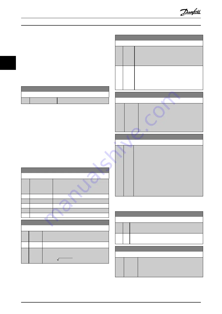
3.13 Main Menu - Data Readouts 2 - Group
18
Parameters in this group are array parameters, where up to
10 fault logs can be viewed. [0] is the most recent logged
data, and [9] the oldest. Error codes, values, and time
stamp can be viewed for all logged data
3.13.1 18-1* Fire Mode Log
18-10 FireMode Log:Event
Range:
Function:
0
*
[0 - 255 ]
View Firemode event.
3.14 Main Menu - FC Closed Loop - Group
20
This parameter group is used for configuring the closed
loop PI Controller, that controls the output frequency of
the frequency converter.
3.14.1 20-0* Feedback
This parameter group is used to configure the feedback
signal for the frequency converter’s closed loop PI
Controller.
20-00 Feedback 1 Source
Option:
Function:
This parameter defines which input is
used as the source of the feedback
signal.
[0]
*
No function
[1]
Analog Input 53
[2]
Analog Input 54
[3]
Pulse input 29
[100] Bus Feedback 1
20-01 Feedback 1 Conversion
Option:
Function:
This parameter allows a conversion function to
be applied to Feedback 1.
[0]
*
Linear
[0] Linear
has no effect on the feedback.
[1]
Square
root
[1] Square root
is commonly used when a
pressure sensor is used to provide flow feedback
(
(
flow ∝ pressure)
).
3.14.2 20-8* PI Basic Settings
Parameters for configuring the Process PI control.
20-81 PI Normal/ Inverse Control
Option:
Function:
[0]
*
Normal Causes the frequency converter’s output frequency
to decrease when the feedback is greater than the
setpoint reference. This is common for pressure-
controlled supply fan and pump applications.
[1]
Inverse Causes the frequency converter’s output frequency
to increase when the feedback is greater than the
setpoint reference. This is common for
temperature-controlled cooling applications, such
as cooling towers.
20-83 PI Start Speed [Hz]
Range:
Function:
0 Hz
*
[ 0 -
200.0
Hz]
Enter the motor speed to be attained as a start
signal for commencement of PI control. Upon
power up, the frequency converter operates
using speed open loop control. When the
Process PI start speed is reached, the frequency
converter changes to PI control.
20-84 On Reference Bandwidth
Range:
Function:
5 %
*
[0 -
200
%]
When the difference between the feedback and the
setpoint reference is less than the value of this
parameter, the frequency converter’s display shows
“Run on Reference”. This status can be
communicated externally by programming the
function of a digital output for
[8] Run on
Reference/No Warning
. In addition, for serial
communications, the On Reference status bit of the
frequency converter’s Status Word is high (1).
The
On Reference Bandwidth
is calculated as a
percentage of the setpoint reference.
3.14.3 20-9* PI Controller
20-91 PI Anti Windup
Option: Function:
[0]
Off Continue regulation of an error even when the output
frequency cannot be increased or decreased.
[1]
*
On Cease regulation of an error when the output
frequency can no longer be adjusted.
20-93 PI Proportional Gain
Range:
Function:
0.50
*
[0 -
10 ]
Enter the process controller proportional gain.
Quick control is obtained at high amplification.
However if amplification is too great, the
process may become unstable.
Parameters
VLT
®
HVAC Basic Drive FC 101 Programming Guide
74
MG18B302 - Rev. 2013-09-02
3
3
Summary of Contents for VLT HVAC Basic Drive FC 101
Page 2: ......
Page 104: ...www danfoss com drives MG18B302 130R0221 MG18B302 Rev 2013 09 02...


