


Function
Setting
5-15 Terminal 33 Digital
Input
[80] PTC Card 1
[4] PTC 1 Alarm
Check that the default value fulfils
the requirement from Motor name
plate. If not -use sine wave filter.
14-26 Trip Delay at Inverter
Fault
0
Table 3.8 Parameters
CAUTION
It is mandatory to compare the minimum switching
frequency requirement stated by the motor manufacturer
to the minimum switching frequency of the frequency
converter, the default value in
. If
the frequency converter does not meet this requirement, a
sine wave filter must be used.
More information about ATEX ETR Thermal Monitoring can
be found in the Application Note MN33GXYY.
3.3.10.5 Klixon
The Klixon type thermal circuit breaker uses a KLIXON
®
metal dish. At a predetermined overload, the heat caused
by the current through the disc causes a trip.
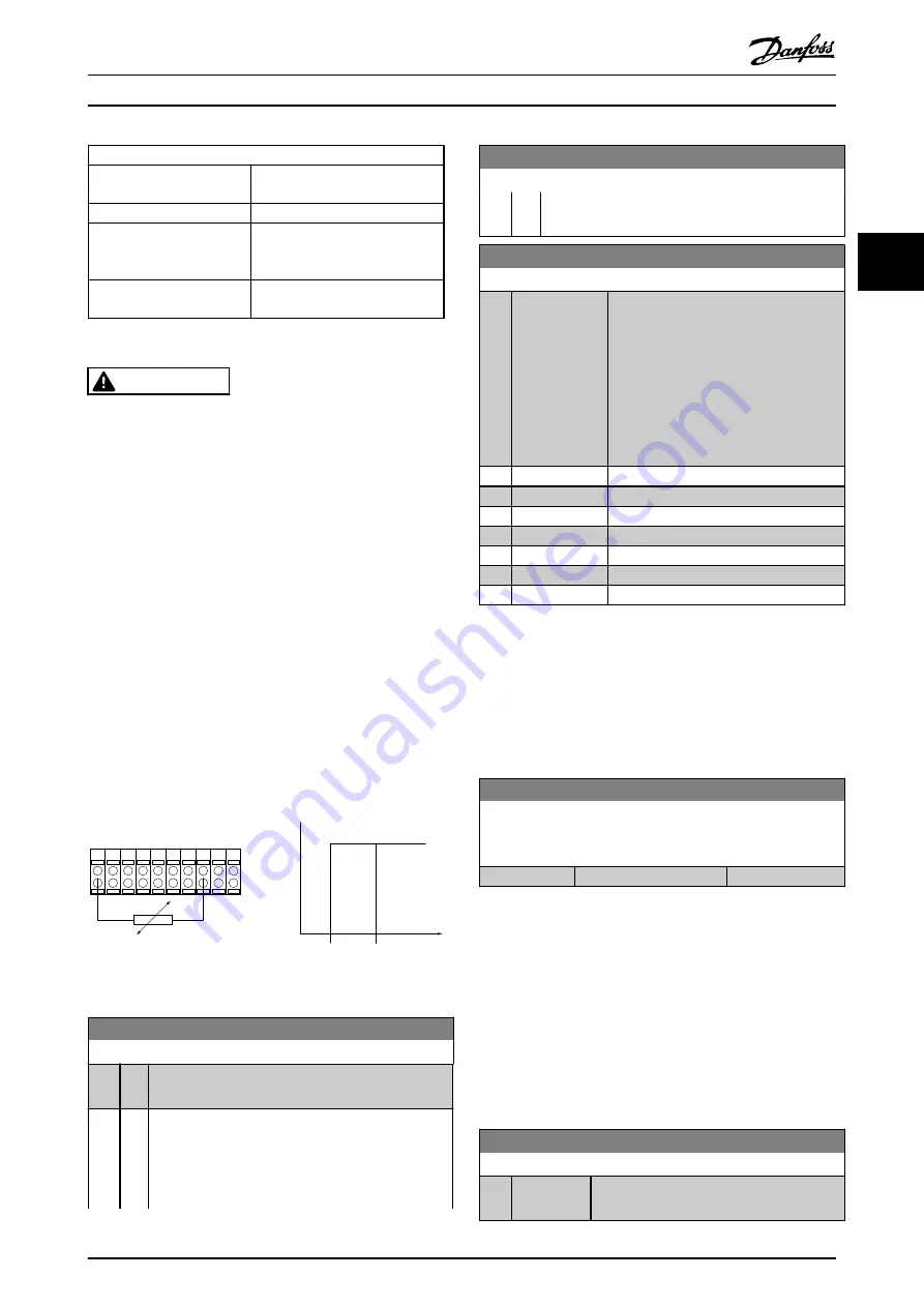
Using a digital input and 24 V as power supply:
Example: The frequency converter trips when the motor
temperature is too high
Parameter set-up:
Set
to
[2] Thermistor Trip
Set
to
[6] Digital Input
PTC / Thermistor
OFF
ON
+24V
12 13 18
37
32
A
27
19
29
33
B
20
GND
R
<6.6 k Ω >10.8 k Ω
130BA151.11
Illustration 3.17
1-91 Motor External Fan
Option: Function:
[0]
*
No No external fan is required, i.e. the motor is derated at
low speed.
[1]
Yes Applies an external motor fan (external ventilation), so
no derating of the motor is required at low speed. The
upper curve in graph above (fout = 1 x fM,N) is
followed if the motor current is lower than nominal
motor current (see
1-24 Motor Current
). If the motor
1-91 Motor External Fan
Option: Function:
current exceeds nominal current, the operation time
still decreases as if no fan were installed.
1-93 Thermistor Source
Option:
Function:
Select the input to which the thermistor
(PTC sensor) should be connected. An
analog input option [1] or [2] cannot be
selected if the analog input is already in
use as a reference source (selected in
3-15 Reference 1 Source
,
3-16 Reference 2
Source
or
3-17 Reference 3 Source
).
When using MCB 112, choice
[0] None
must always be selected.
[0]
*
None
[1]
Analog input 53
[2]
Analog input 54
[3]
Digital input 18
[4]
Digital input 19
[5]
Digital input 32
[6]
Digital input 33
NOTE
This parameter cannot be adjusted while the motor is
running.
NOTE
Digital input should be set to
[0] PNP - Active at 24 V
in
5-00 Digital I/O Mode
.
1-94 ATEX ETR cur.lim. speed reduction
FC 302 only.
Only visible if
is set to [20].
Range:
Function:
0.0 %
*
[0.0 - 100.0 %]
The reaction for operating in Ex-e current limit must be
configured.
0%: The frequency converter does not change anything
besides issuing warning 163 ATEX ETR cur.lim.warning.
>0%: The frequency converter issuing warning 163 and
reduces motor speed following ramp 2 (parameter group
3-5*).
Example:
Actual reference = 50 RPM
1-94 ATEX ETR cur.lim. speed reduction
= 20%
Resulting reference = 40 RPM
1-95 KTY Sensor Type
Option:
Function:
Select the used type of KTY sensor. FC 302
only.
Parameter Descriptions
VLT
®
AutomationDrive Programmming Guide
MG33ME02 - VLT
®
is a registered Danfoss trademark
49
3
3