


3.2.6 Control Structure in Flux with Motor Feedback
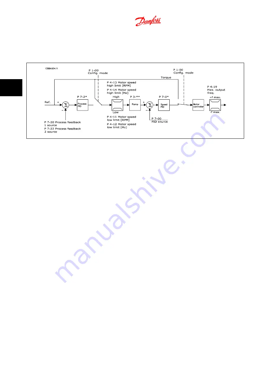
Control structure in Flux with motor feedback configuration (only available in AutomationDrive FC 302):
In the shown configuration, par. 1-01
Motor Control Principle
is set to “Flux w motor feedb [3]” and par. 1-00
Configuration Mode
is set to “Speed closed-
loop [1]”.
The motor control in this configuration relies on a feedback signal from an encoder mounted directly on the motor (set in par. 1-02
Flux Motor Feedback
Source
).
Select “Speed closed-loop [1]” in par. 1-00
Configuration Mode
to use the resulting reference as an input for the Speed PID control. The Speed PID control
parameters are located in par. group 7-0*.
Select “Torque [2]” in par. 1-00
Configuration Mode
to use the resulting reference directly as a torque reference. Torque control can only be selected in
the
Flux with motor feedback
(par. 1-01
Motor Control Principle
) configuration. When this mode has been selected, the reference will use the Nm unit.
It requires no torque feedback, since the actual torque is calculated on the basis of the current measurement of the adjustable frequency drive.
Select “Process [3]” in par. 1-00
Configuration Mode
to use the process PID control for closed-loop control of, e.g., speed or a process variable in the
controlled application.
3.2.7 Internal Current Control in VVC
plus
Mode
The adjustable frequency drive features an integral current limit control which is activated when the motor current, and thus the torque, is higher than
the torque limits set in par. 4-16
Torque Limit Motor Mode
, par. 4-17
Torque Limit Generator Mode
and par. 4-18
Current Limit
.
When the adjustable frequency drive is at the current limit during motor operation or regenerative operation, the adjustable frequency drive will try to
get below the preset torque limits as quickly as possible without losing control of the motor.
3.2.8 Local (Hand On) and Remote (Auto On) Control
The adjustable frequency drive can be operated manually via the local control panel (LCP) or remotely via analog and digital inputs and serial bus.
If allowed in par. 0-40
[Hand on] Key on LCP
, par. 0-41
[Off] Key on LCP
, par. 0-42
[Auto on] Key on LCP
, and par. 0-43
[Reset] Key on LCP
, it is possible
to start and stop the adjustable frequency drive via the LCP using the [Hand ON] and [Off] keys. Alarms can be reset via the [RESET] key. After pressing
the [Hand ON] key, the adjustable frequency drive goes into hand mode and follows (as default) the local reference that can be set using arrow key on
the LCP.
3 Introduction to AutomationDrive FC 300
FC 300 Design Guide
3-8
MG.33.BC.22 - VLT
®
is a registered Danfoss trademark
3


