


Programming example 2
Par. 5-19 Terminal 37 Safe Stop
[6]
PTC 1 & Relay Alarm
In case the motor temperature is too high, or in the event of a PTC failure, the MCB 112 activates the Safe Stop
of the FC 302 (Safe Stop terminal 37 goes LOW (active) and digital input 33 goes HIGH (active)). This parameter
decides the consequence of the Safe Stop. With this option, the FC 302 coasts, and "PTC 1 SafeStop [A71]" is
displayed in the LCP. The drive must be manually reset from LCP, digital input or serial communication bus when
the conditions of the PTC are acceptable again (temperature of motor has dropped). An emergency stop can also
activate the Safe Stop of the FC 302 (Safe Stop terminal 37 goes LOW (active) but digital input 33 is not triggered
by MCB 112 X44/10 as the MCB 112 did not need to activate the Safe Stop; therefore, digital input 33 remains
HIGH (inactive)).
Par. 5-15 Terminal 33 Digital Input
[80] PTC Card 1
Connects the digital Input of terminal 33 in the FC 302 to the MCB 112, which makes it possible for the MCB 112
to indicate when Safe Stop has been activated from here.
Alternatively, par. 5-19 could be set to [7] (PTC 1 & Relay Warning), which means an automatic restart when the conditions of the PTC circuit and/or
emergency stop circuit have returned to normal. The choice depends on the demands of the customer. Also, the setting of parameter 5-19 could be [8]
(PTC 1 & Relay A/W) or [9] (PTC 1 & Relay W/A), which are combinations of alarm and warning. The choice depends on the needs of the customer.
NOTE!
Selection [4] – [9] in par. 5-19 will only be visible in case the MCB 112 is plugged into the B-option slot.
Take care that the DI that is set to [80] is not also configured as Thermistor Resource (motor protection) in par. 1-93.
Please refer to
Parameter settings for external safety device in combination with MCB 112
in the
Introduction to FC 300
section for more information
about the combination.
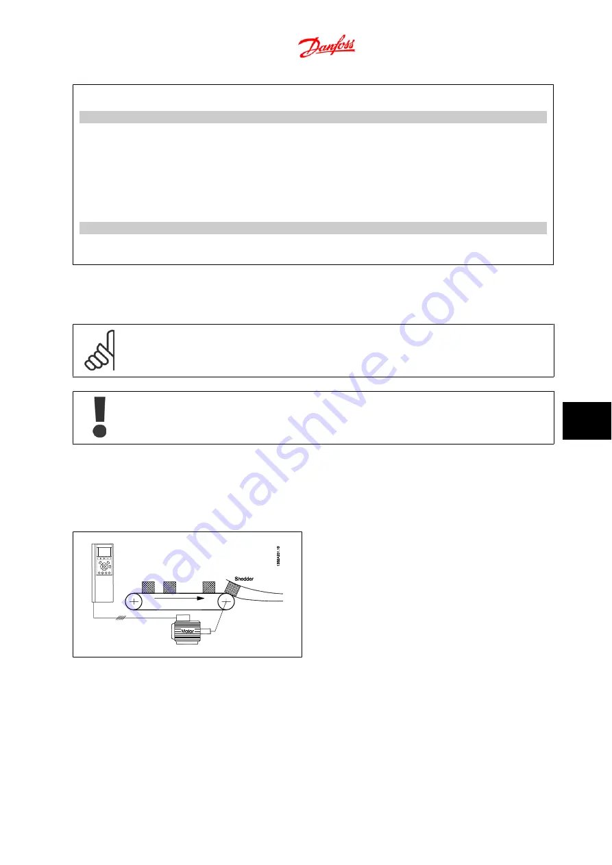
9.1.13 Torque Control Open-loop
A conveyor belt feeds bales forward into a shredder at constant force,
regardless of the conveyor speed. If there is a space between the bales,
the conveyor belt must move the next bale to the shedder as fast as
possible.
Optimization of the torque control. After setting the basic settings, the
factory setting is optimized for most processes. It is rarely necessary to
optimize the
torque proportional gain
in par. 7-12 and the torque inte-
gration time in par. 7-13.
Feedback
The feedback signal is an estimated torque, calculated by the adjustable
frequency drive on the basis of the current values measured
Reference
The reference is in Nm. A minimum and a maximum reference can be set
(par. 6-14 and 6-15) which limit the sum of all references. The reference
range cannot go beyond the feedback range.
Speed limit function
Speed limit can be set in par. 6-20 to 6-25
FC 300 Design Guide
9 Application Examples
MG.33.BC.22 - VLT
®
is a registered Danfoss trademark
9-9
9


