Outline of Control (Indoor Unit)
SiUS331604E
55
Functions and Control
6.3
Thermostat Control
6.3.1 Without the Optional Infrared Floor Sensor
Whether the thermostat is turned on or off is determined by the difference between the remote controller set
temperature and the actual detected room temperature (
∗
1).
•
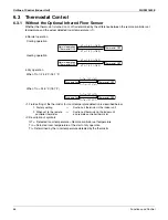
Normal operation
· Cooling operation
· Heating operation
•
Dry operation
· When Tro
≤
24.5°C (76.1°F)
· When Tro > 24.5°C (76.1°F)
∗
1: Field setting of the thermistor for room temperature detection is described below.
∗
2: Description of symbols
∆
T = Detected room temperature – Remote controller set temperature
Tro = Detected room temperature at the start of dry operation
Tr = Determined by the room temperature detected by the thermistor
1. Factory setting
→
Suction air thermistor in the indoor unit
2. When set to the remote
controller thermistor
→
Suction air thermistor in the indoor unit
and remote controller thermistor
Thermostat OFF
Normal operation
(Thermostat ON)
∆
T
≤
–1.0˚C (–1.8˚F)
∆
T
≥ +
1.0˚C (
+
1.8˚F)
Thermostat OFF
Normal operation
(Thermostat ON)
∆
T
≥ +
1.0˚C (
+
1.8˚F)
∆
T
≤
–1.0˚C (–1.8˚F)
Thermostat OFF
Dry operation
Tr
<
Tro – 1.0˚C (–1.8˚F)
Tr
>
Tro + 1.0˚C (
+
1.8˚F)
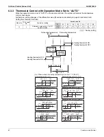
Thermostat OFF
Dry operation
Tr
<
Tro – 1.5˚C (–2.7˚F)
Tr
>
Tro + 1.5˚C (+2.7˚F)
Summary of Contents for VRV IV-S RXTQ-TAVJU Series
Page 1: ...Service Manual SiUS331604E RXTQ36 48 60TAVJU Heat Pump 60 Hz...
Page 254: ...Wiring Diagrams SiUS331604E 241 Appendix RXTQ48TAVJU 3D100496A...
Page 255: ...SiUS331604E Wiring Diagrams Appendix 242 RXTQ60TAVJU 3D100497A...
Page 260: ...Wiring Diagrams SiUS331604E 247 Appendix FXEQ07 09 12 15 18 24PVJU C 3D098557...
Page 267: ...SiUS331604E Wiring Diagrams Appendix 254 FXTQ12 18 24 30 36 42 48 54PAVJU 3D065036G...
Page 270: ...Wiring Diagrams SiUS331604E 257 Appendix VAM1200GVJU 3D073270C...
Page 271: ...Revision History Month Year Version Revised contents 06 2016 SiUS331604E First edition...


