User’s Manual
76
By clicking
, the Camera List page is displayed. For details about adding the remote devices, see
"5.6 Configuring Remote Devices."
5.2.3
Navigation Bar
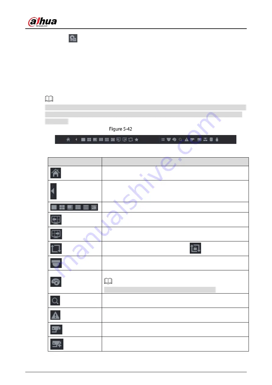
You can access the functions to perform operations through the function icons on the navigation bar.
For example, you can access Main Menu and switch window split mode.
The navigation bar is disabled by default. It does not appear in the live view screen until it is enabled.
To enable it, select Main Menu > SYSTEM > General > Basic, enable the Navigation Bar, and then
click Apply.
Navigation bar
Table 5-9
Navigation bar description
Icon
Function
Open Main Menu.
Expand or condense the navigation bar.
Select view layout.
Go to the previous screen.
Go to the next screen.
Enable tour function. The icon switches to
.
Open the PTZ control panel. For details, see "5.4 Controlling PTZ
Cameras."
Open the Image page.
This function is supported only in single-channel layout.
Open the record search page. For detail, see "5.9 Playing Back Video."
Open the Alarm Status page to view the device alarm status. For
details, see "5.21.3 Viewing Event Information."
Open the CHANNEL INFO page to display the information of each
channel.
Open the Camera List page. For details, see "5.6.1 Adding Remote
Summary of Contents for DH-XVR71 H-4K-I2 Series
Page 24: ...User s Manual 15 Fasten screws...
Page 67: ...User s Manual 58 TCP IP Configure the settings for network parameters...
Page 103: ...User s Manual 94 Main menu...
Page 189: ...User s Manual 180 Details Click Register ID Register ID Click to add a face picture...
Page 212: ...User s Manual 203 Search results Click the picture that you want to play back Playback...
Page 239: ...User s Manual 230 Details Click Register ID Register ID Click to add a face picture...
Page 314: ...User s Manual 305 Main stream Sub stream...
Page 347: ...User s Manual 338 Update Click Update Browse Click the file that you want to upgrade Click OK...
Page 362: ...User s Manual 353 Legal information...
Page 388: ...User s Manual 379 Appendix Figure 7 7 Check neutral cable connection...
Page 394: ...User s Manual...


