User’s Manual
22
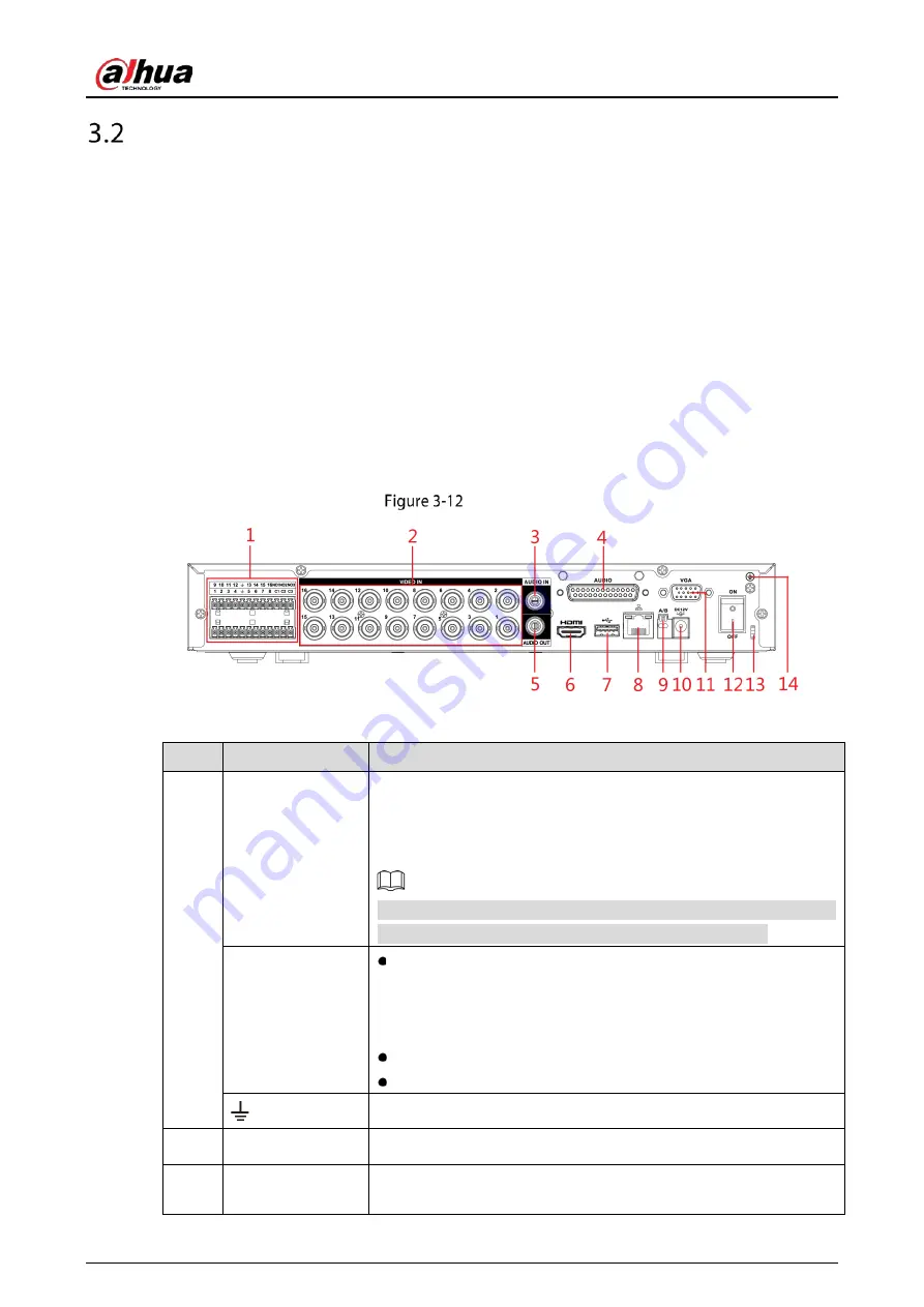
Rear Panel
3.2.1
DH-XVR5104H-I/DH-XVR5108H-I/DH-XVR5116H-I/DH-
XVR51xxH-I2/DH-XVR51xxHE-I2/DH-XVR51xxH-4KL-I2/DH-
XVR51xxHE-4KL-I2/DH-XVR51xxH-I3/DH-XVR51xxHE-I3/DH-
XVR51xxH-4KL-I3/DH-XVR51xxHE-4KL-I3/DH-XVR7104HE-4KL-I/DH-
XVR7108HE-4KL-I/DH-XVR7116HE-4KL-I/DH-XVR71xxH-4K-I2/DH-
XVR71xxHE-4K-I2
Rear panel
Table 3-11
Rear panel description
No.
Port Name
Function
1
Alarm input port
1–16
Four groups of alarm input ports (Group 1: port 1 to port 4; Group 2:
port 5 to port 8; Group 3: port 9 to port 12; Group 4: port 13 to port
16). These ports receive the signal from the external alarm source.
There are two types: NO (Normally Open) and NC (Normally Closed).
When your alarm input device is using external power, make sure the
alarm input device and the Device have the same ground.
Alarm output port
1–3 (NO1–NO3;
C1–C3)
Three groups of alarm output ports (Group 1: port NO1–C1,
Group 2: port NO2–C2, Group 3: port NO3–C3). These ports
output alarm signal to the alarm device. Make sure power
supply to the external alarm device.
NO: Normally open alarm output port.
C: Alarm output public end.
Ground.
2
Video input port
Connects to analog camera to input video signal.
3
Audio input port
Receives audio signal output from the devices such as microphone.
It corresponds to video input port 1.
Summary of Contents for DH-XVR71 H-4K-I2 Series
Page 24: ...User s Manual 15 Fasten screws...
Page 67: ...User s Manual 58 TCP IP Configure the settings for network parameters...
Page 103: ...User s Manual 94 Main menu...
Page 189: ...User s Manual 180 Details Click Register ID Register ID Click to add a face picture...
Page 212: ...User s Manual 203 Search results Click the picture that you want to play back Playback...
Page 239: ...User s Manual 230 Details Click Register ID Register ID Click to add a face picture...
Page 314: ...User s Manual 305 Main stream Sub stream...
Page 347: ...User s Manual 338 Update Click Update Browse Click the file that you want to upgrade Click OK...
Page 362: ...User s Manual 353 Legal information...
Page 388: ...User s Manual 379 Appendix Figure 7 7 Check neutral cable connection...
Page 394: ...User s Manual...


