background image

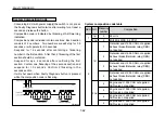
If ECU power is on (ignition on), wait for at least a second
and press Faulty Diagnosis button once (0.5~5secs)and
release it.
Fault code transfer will happen.
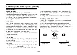
Faulty code is indicated with brief flicker of ABS warning
indication lamp.
Fault codes indicating details of faults are divided into two
flickering.
The first flicker(apx 0.5 secs each) indicate 

the first

number

, and the second flicker (apx 0.5 secs each) after

1.5 seconds suspension indicate 

the second number

.

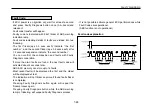
You can confirm the composition and faults with Faulty
Diagnosis code table.
If more than two faults are found, the next fault code will
activated about 4 seconds later.
ABS ECU memory can store upto 16 faults.
Most recent fault will be displayed the first and the oldest
will be displayed at last.
The indication will not flicker anymore if found faults flicker
is completed.
Pressing Faulty Diagnosis button again will repeat the
flicker process again.
Pressing Faulty Diagnosis button while the ABS warning
lamp is  flickering, will suspend Faulty Diagnosis process.

It is not possible activate general ECU performances while
Fault Codes are operational.
(ABS function is not operational)

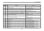
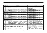
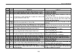
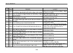
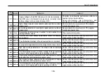
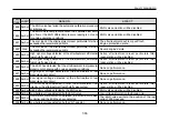
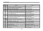
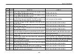
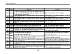
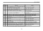
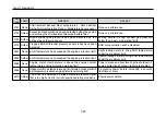
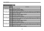
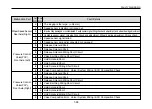
Fault code explanation

7-63

FAULTY DIAGNOSIS

Fault Code

OM-B295E

·

·

·

·

·

·
·

·

·

Summary of Contents for BS Series

Page 1: ......

Page 2: ...riving at high speed long haul The initial change is at 1 000 km Replace it every 20 000 km Driving in downtown short haul Replace it every 30 000 km Driving at high speed long haul The initial change...

Page 3: ...initial change at 5 000km Inspection Refill Every 4 000km after the initial one at 1 000km Replacement Every 24 000km after the initial change at 5 000km Inspection refill Every 4 000km after the ini...

Page 4: ...t of the product and we will be grateful if you understand that our company has no obligation to apply it for delivered vehicles about changed contents Please read and familiarize this manual before d...

Page 5: ...ual present this Warranty to any authorized Daewoo Bus dealer and request that the appropriate service be performed We sincerely hope that you will be delighted with your Daewoo Bus and that it brings...

Page 6: ...eriod set forth in paragraph 1 hereof without charge to the owner of the Daewoo Bus 3 What is not covered This warranty shall not apply to or include any of the following a Repair or replacement requi...

Page 7: ...responsibility You should retain evidence that proper maintenance has been performed on your Daewoo Bus Claims made during the warranty period will not quality under the warranty if resulting from lac...

Page 8: ...SUGGESTIONS DAEWOO PRODUCTS Please write down any suggestions concerning Daewoo products that help Manufacturee to develop Daewoo products...

Page 9: ...card should be sent to Manufacturer by Dealer Owner Service No O S No Model Street City Date of Delivery Shipping Date Owner s Phone No Country Vehicle Ident No VIN Engine No Mileage at Delivery Owne...

Page 10: ...Repair and Replacement by Warranty Should any defects in material or workmanship occur within the period said part will be repaired or replaced without cost to you after certification of the Daewoo de...

Page 11: ...ide booklet I also took notice of the warranty terms as presented in this booklet The warranty commencess as of the date of delivery Date Owner s Signature cut here O S NO We hereby certify to have de...

Page 12: ...lyte level leakage terminal check 10 Hose connections check 11 Air cleaner check Clean 12 Fuel filter check and water drain CHASSIS UNDERBODY 1 Front suspension check 2 Manual transmission leakage che...

Page 13: ...DEALER IMPRINT...

Page 14: ...e information in this manual could be changed without notice and we would not offer a note or apply this changed situation for delivered vehicle The parts and accessories which are not originated from...

Page 15: ...CONTENTS INTERIOR EXTERIOR VIEW AND SPECIFICATIONS SAFETY CAUTIONS DEVICE CONTROL TIPS START UP DRIVING EMERGENCY AID VEHICLE INSPECTION AND MAINTENANCE FAULTY DIAGNOSIS...

Page 16: ...SPECIFICATIONS AND SERVICE DATA Vehicle Specifications VIN 1 2 Engine Number 1 2 2 INTERIOR EXTERIOR VIEW OF VEHICLE Exterior View of Vehilce 1 3 3 SPECIFICATIONS Vehicle 1 7 Engine 1 9 Chassis Number...

Page 17: ...The vehicle specifications plate is placed on the control panel to the left side of a driver The engine number is stamped on the right side of an engine block The chassis number is stamped on the upp...

Page 18: ...ow 13 Engine Room Air Rotation Hole 14 Back Lamp 15 Towing Hook 16 Fuel Inlet 17 Entrance Door lock 18 Door Opening and Shutting Switch 19 Marker Lamps 20 Auto Ventilator 21 Antenna 22 Rear combinatio...

Page 19: ...gnal 10 Fog Lamps 11 Front Combination Lamps 12 Side Window 13 Engine Room Air Rotation Hole 14 Back Lamp 15 Towing Hook 16 Entrance Door lock 17 Door Opening and Shutting Switch 18 Marker Lamps 19 TV...

Page 20: ...l Panel 9 Idle Speed Actuator and Cruise Switch 10 Gearshift 11 Wiper Exhaust Brake Controls 12 Horn 13 Steering Wheel 14 Turn Signal Headlamp Controls 15 Parking Brake 16 Clutch Oil Reserve 17 Engine...

Page 21: ...7 Gearshift 8 Accelerator Pedal 9 Brake Pedal 10 Clutch Pedal 11 Horn 12 Steering Wheel 13 Parking Brake 14 Clutch Oil Reserve 15 Turn Signal Headlamp Controls 16 Wiper Exhaust Brake Controls 17 Engin...

Page 22: ...0 BS106 10 590 2 490 3 200 2 050 1 853 2 100 3 110 5 200 BS110CN 11 010 2 490 3 005 2 096 1 836 2 410 3 110 5 400 BS120CN 11 990 2 490 3 060 2 096 1 836 2 600 3 110 6 100 BC211M 11 000 2 490 3 235 2 0...

Page 23: ...110 6 500 BH116 11 550 2 490 3 225 2 050 1 853 2 225 3 110 6 100 BH117 11 750 2 490 3 395 2 050 1 853 2 425 3 110 6 100 BH119 12 000 2 490 3 395 2 050 1 853 2 425 3 110 6 350 BH120 12 000 2 490 3 415...

Page 24: ...0 2 100 125 1 260 340 ps 340 2 100 145 1 260 360 ps 390 2 100 145 1 260 390 ps 14 618 390 2 200 160 1 300 11 051 Model Type Piston displacement Power ouput ps rpm Torque kg m rpm Combustion sequence D...

Page 25: ...2 100 192 1 200 400 ps 400 1 900 173 1 200 430 ps 430 1 900 192 1 200 In line 4 stroke water cooled supercharging air cooled type 90 V type 4 stroke water cooled supercharging air cooled type 5 900 1...

Page 26: ...00R20 16PR 8 1 7 4 7 00T 20 Steel Wheel 70 80 10 hole 70 85 8 hole AL Wheel 60 70 10 hole 62 70 8 hole Air pressure kgf cm2 Tire size Wheel size Wheel Torque kg m Front wheel Rear wheel 11 00 20 16PR...

Page 27: ...Directions for Engine Room Maintenance 2 6 5 DIRECTIONS FOR TURBOCHARGER INSTALLED VEHICLES Turbocharger 2 7 6 RISKS AND OTHER CAUTIONS Do Not Place Flamable or Explosive Articles in the Car 2 8 7 CAU...

Page 28: ...is acclimated New vehicle care will bring out vehicle s optimal efficiency and also lengthen the vehicle life Warm up engine after the ignition Avoid sudden star or sudden acceleration Do not exceed t...

Page 29: ...d the feet should be able to fully step on padals The center of the headrest should be adjusted to eye level The seat should be adjusted with the lever according to the driver s body size Remove any d...

Page 30: ...f any faults are found immediately take an appropriate action and get proper maintenance Please park at safe locations and activate parking break gearshift should be set on 1 for uphill and R for down...

Page 31: ...d handling malfunction 2 5 SAFETY CAUTIONS Do Not Talk on Mobile Phone Do Not Drive with the Doors Open Do Not Turn the Engine Off While Driving OM B028 OM B029 OM B032 3 SAFETY CAUTIONS WHEN DRIVING...

Page 32: ...than inspection and maintenance purposes Close the door or the window The bus should be washed from top to bottom High pressure water should used to clean the bottom and inner fender Sponges or such...

Page 33: ...nly suspending the engine at a wide open throttle condition the high temperature from the exhaust gas and oil might cause the turbo charger s lubrication compartment to leak You should therefore turn...

Page 34: ...ishers should always be equipped in the vehicle If fire occurs within the bus do not panic and safely guide the passengers out Extinguish the fire afterwards How to use the fire extinguisher a Face ag...

Page 35: ...kgf cm2 Under the gas pressure of 30kgf cm2 the CNG lamp light on This is when the refueling in needed 2 9 7 CAUTIONS FOR CNG VEHICLES SAFETY CAUTIONS Compressed Natural Gas CNG CNG Recharge Cautions...

Page 36: ...s manual isolation valve Transport the injured to a safe place and check whether there is a gas leakage 2 10 SAFETY CAUTIONS Maintenance Directions How to Handle Accidents CAUTION Do not touch oil dra...

Page 37: ...ve the passengers evacuated off the vehicle Close the fuel line s manual isolation valve Notify the authorities immediately 2 11 SAFETY CAUTIONS REFERENCE Prsssure relief valve is installed in this ve...

Page 38: ...3 10 Adjusting Driver s Seat 3 11 4 INSTRUMENT PANEL Speedometer 3 20 Engine RPM Meter 3 20 Fuel Gauge 3 20 Coolant Temperature Gauge 3 21 Air Pressure Gauge 3 22 Voltmeter 3 23 Remote Control Key OPT...

Page 39: ...0 7 OTHER DEVICES Audio OPTION 3 63 Tachograph OPTION 3 63 Refrigerator Heating Cabinet Water Cooler Water Heater OPTION 3 63 Toilet OPTION 3 64 Washer Fluid Switch 3 39 Parking Brake 3 39 Engine Diag...

Page 40: ...direction indication blinks twice Door close The door opens when remote control button is double pressed within 1 5 seconds The direction indication blinks once 3 3 1 HOW TO USE THE KEY DEVICE CONTROL...

Page 41: ...en close the door automatically Getting Off You can open close the door automatically with interior switch 3 4 2 HOW TO OPEN CLOSE THE DOOR DEVICE CONTROL TIPS Opening Closing the Entrance Door Door L...

Page 42: ...oing to leave the door open The automatic door open close may malfunction due to low air pressure caused by air leakage if you leave the bus parked for a long time WARNING Do never operate the door op...

Page 43: ...art of the switch to lower the window to the left of the driver s seat Press the upper part of the switch to raise the window If there is a lock unlock it with a key and pull the grip to open the door...

Page 44: ...door with a key before operating The door opens if you pull and raise the lower part of the door Securely close the door when closing Lock it with a key or switch if there is any locking device Drive...

Page 45: ...lt in injury CAUTION Using unapproved fuels could result in serious damage to the engine Only use approved standard fuels We are not held responsible for any damages occurred from using unapproved hue...

Page 46: ...a clicking sound Quarter Glass Hold the rear part of the lock and pull it to open Close the door and press the rear part of the fixing device 3 9 DEVICE CONTROL TIPS Side Window OM B415 OM H242 CAUTI...

Page 47: ...ve the steering wheel to the front back and up down c Turn locked wheel to clockwise and fix it completely Horn Button Horn button is placed in the middle of the wheel Use it in unexpected or dangerou...

Page 48: ...ch to backward Always set up the back of the seat straight and seat in right posture because one can have serious injury or lose life from body slipping under the safety belt in a clash accident Check...

Page 49: ...ure Release the locking lever to lock the backrest Seat Pan Angle Adjustment To adjust the angle of the seat pan pull the left handle upwards The seat pan can be moved to the desired position by simul...

Page 50: ...the upper and lower area of the backrest upholstery can be adjusted individually The air compartments will be filled by setting the respective switch to and emptied by setting it to 3 13 DEVICE CONTR...

Page 51: ...Release the locking lever to lock the backrest Seat Pan Angle Adjustment To adjust the angle of the seat pan pull the left handle upwards The seat pan can be moved to the desired position by simultan...

Page 52: ...wards Vertical Shock Absorber Adjustment The vertical vibration behavior of the seat can be adjusted continuously from soft to hard by using the turning knob 1 Soft shock absorption 2 Medium shock abs...

Page 53: ...switch to the air compartments will be filled By setting it to they will be emptied Lumbar Support With the front 1 and back 2 switch the curvature in the upper and lower area of the backrest upholste...

Page 54: ...e not fasten driver s seat belt while main switch is ON Catch a latch plate 1 pull it over the shoulder and fix to buckle 2 Ensure that belt is not twisted and the back of chair is not leaning backwar...

Page 55: ...ny additional devices on the seat belt It could reduce the safety of the seat belt Do not wear the seatbelt loosely Check the seatbelt and related parts for safety reasons If any faults are found imme...

Page 56: ...auge EURO II III ISM CNG Engine 5 Urea Gauge EURO IV Engine DL06 DL08 DV11 6 Air Pressure Gauge Rear 7 Speedometer 8 Turn Signal 9 Bulb Check Switch ABS Self Diagnosis Switch 10 Engine RPM Meter 11 Pi...

Page 57: ...ehicles This gauge indicates the remaining fuel amount in the fuel tank and should be refilled when the indicator indicates near the E line Always operate the vehicle with sufficient fuel 3 20 DEVICE...

Page 58: ...n the gas tank s temperature is 13 F 210 E 21 Full Tank Remaining Pressure Status Short on gas REFERENCE Since the vehicle consumes gaseous fuel the pressure varies according to the storage tank s tem...

Page 59: ...indicator of the gauge is within the normal range before operating the vehicle WARNING Frequent breaking will reduce the air pressure drastically Always maintain safe distance When the indicator indi...

Page 60: ...re level falls below the normal range A warning lamp turns on and an alarm sound when the vehicle has insufficient amount of engine oil or when the oil pressure falls 3 23 DEVICE CONTROL TIPS Voltmete...

Page 61: ...DL06 DL08 DV11 Bulb Check Switch ABS Self Diagnosis Button WARNING If you continue driving when the urea level is lower than 5 it may result in output power engine parts may be affected negatively pl...

Page 62: ...3 25 DEVICE CONTROL TIPS Indicator Warning Lamps OM B523 The indicator and warning lamps for options that are not applicable to your vehicle or that are not selected by the owner do not operate...

Page 63: ...g Operation Indicator Lamp Entrance Door Open Indicator Lamp Passenger Stop Indicator Lamp Color Name Upper Pilot Indicator Lamps Position A3 B3 C3 D3 E3 F3 G3 H3 A4 B4 C4 D4 E4 F4 G4 H4 Amber Amber R...

Page 64: ...ously having the engine operate Engine Oil Pressure Warning Lamp The lamp turns on when the battery main switch is in the ON position and turns off when the engine starts and the engine oil pressure r...

Page 65: ...insufficient air in the rear wheel brake tank Air Tank Parking Brake Air Pressure Warning Lamp The lamp turns on when the air pressure falls below 6 2 kgf cm2 due to insufficient air in the parking br...

Page 66: ...on Indicator Lamp The lamp turns on when the auto greaser device is operate Auto greaser operation time depends on the control operation time of each auto greaser model Insufficient Fuel Warning Lamp...

Page 67: ...n when the entrance door is open Passenger Stop Indicator Lamp The lamp turns on with a buzzer when a passenger presses the stop button inside the vehicle Subsidiary Brake Operation Indicator Lamp The...

Page 68: ...cator Lamp Amber Applicable to vehicles equipped with a retarder The lamp turns on when the brake are applied Neutral Gear Position Indicator Lamp The lamp turns on when the gear is in the neutral pos...

Page 69: ...Lamp Amber The lamp Turns on in the instrument panel when the main switch is pressed and the key is in the ON position and turns off when the engine is started The lamp remains turned off while the en...

Page 70: ...the indication is still on visit the nearest service center ISM Engine The indication is on when there is a problem with the engine system You must visit the nearest service center if the indication i...

Page 71: ...ven after closing the door check the door lock and lock the door firmly Low Beam Operation Indicator Lamp The lamp turns on when the leadlight is activated Speed Control Device Warning Lamp The lamp t...

Page 72: ...turns on when the middle door is opened Rear Door Operation The indicator lamp turns on when the rear door is opened Front Emergency Valve Operation The indicator lamp turns on while the front emerge...

Page 73: ...e Lights 3 36 5 SWITCHES DEVICE CONTROL TIPS Turn Signal Activation Lever Light Switch OM B109 OM B110E CAUTION Leaving the turn signal lamps activated while the engine is turned off may discharge the...

Page 74: ...ginal position and turns of the headlamps Pulling the lever spplies the subsidiary brake and turns on the indicator lamp in the instrument panel Refer to page 4 19 for Subsidiary break 3 37 DEVICE CON...

Page 75: ...rn the middle section of the lever to control the intermittence interval of the wipers while the wiper switch is in the INT position 3 38 DEVICE CONTROL TIPS Emergency Warning Lamp Switch Wiper Switch...

Page 76: ...re that the indicator lamp is off before driving off Pull the parking brake application valve s lever and fix the lever using the LOCK button to have the vehicle in a parked state The parking indicato...

Page 77: ...details Turning the knob clockwise after cold starting of the engine will increase idling speed and thus facilitate quick normalization of the engine coolant temperature Always drive with the knob tur...

Page 78: ...PE C CAUTION CNG buses run on electronically controlled engines which enables rthe engine ECM to automatically control its engine idle rotation speed As a result the switch should be in the IDLE posit...

Page 79: ...y set value is maintained even after the following srating of the engine When the engine si turned off without pressing the Save Return switch it returns to the initial value You must repeat the idle...

Page 80: ...of the clutch pedal Upon activation of the Jake Exhaust brake Upon opening of a door When the vehicle s speed is below 40 km h Upon a fault in the vehicle speed sensor When the number of engine rotati...

Page 81: ...attery main switch by pressing it again after turning off the engine when parking the vehicle after operation Front Entrance Switch Can open and close using switch 3 44 DEVICE CONTROL TIPS Interior El...

Page 82: ...d activate it only in dangerous situations accident or during repair and maintenance Entrance Door Lock Switch This switch will lock unlock the door 3 45 DEVICE CONTROL TIPS OM S125 OM B434 OM B435 OM...

Page 83: ...ctivation of the switch turns on the rear fog lamps when the light switch is in 1st or higher mode when lamps are ON The lamps are turned off when the switch is deactivated to return to the OFF positi...

Page 84: ...ctivation of the switch turns on the destination lamp when the light switch is in 1st or higher mode when tail lamps are ON The lamps are turned off when the switch is deactivated to return to the OFF...

Page 85: ...switch turns on the reading lamps in the passenger seats The lamps are turned off when the switch is deactivated to return to the OFF position Luggage Room Lamps Switch Activation of the switch turns...

Page 86: ...tch Activation of the switch turns on the rack lamps The lamps are turned off when the switch is deactivated to return to the OFF position Driver s Seat Heater Switch The heater in the driver s seat i...

Page 87: ...ctivation of the switch supplies power to the TV VCR Turn on the switches on the TV VCR after activating this switch The power supply is cut off to the TV VCR when the switch is deactivated to return...

Page 88: ...ar of the vehicle through a monitor screen The screen appears when the gear is shifted to reverse position and it disappears when the gear id shifted to any other position The screen is displayed inde...

Page 89: ...r side s side mirror and turn the switch to the right when adjusting the entrance side s side mirror Angle Adjustment Adjust the mirror to the desired angle by moving the switch up down left and right...

Page 90: ...is at ON Connect the mobile phone jack and ear mike jack of mobile phone with the mobile phone connection code For receiving the call Press the communication switch for longer than 0 5 seconds until...

Page 91: ...AC is operated for too long while the car is stopped he engine could be over heated Be reminded of the matter If the AC or fanning function is operated while the engine is off The battery may run out...

Page 92: ...5 Temperature Setup Ascending 6 Temperature Setup Descending 7 Temperature confirming 8 AQS 9 Interior Exterior Unit Selection 10 Dehumidify 11 A Negative Ion 12 Emergency Air Conditioning 3 55 DEVICE...

Page 93: ...ile pressing the switch Temperature Setup The temperature can be adjusted from 17 to 30 by 0 5 units Temperature confirming Interior exterior temperatures are displayed evertime the switch is pressed...

Page 94: ...ings Upon activation of the numbers and set temperature switches the current temperature display changes to the set temperature display which can be controlled within the range of 15 30 During the tem...

Page 95: ...rature by turning the rotary switch Press the air cooler activation button for air cooling and control the power levels using the power level activation buttons The air cooler activation button can on...

Page 96: ...m and increases the fan power The number rotary switch is used to shift fan directions Turning the switch counterclockwise directs the fan toward the front and lower section of the driver and turning...

Page 97: ...stalled as on option Upon pressing in activate button the activate button lamp and the pump button lamp turns on the drive motor and the circulation pump motor activates and also the fan and the fuel...

Page 98: ...pon such action combustion stops and the drive motor and the circulation pump motor stops after about 3 minutes of activation Position the battery main switch to the OFF position after the circulation...

Page 99: ...n will open the rear ventialtion and the fan will spin to exhaust interior air Pressing button will open the ventilation but the fan will not spin The air is ventilated naturally Pressing button will...

Page 100: ...separately supplied manual for more detailed instructions Refer to separately supplied manual for more detailed instructions 3 63 7 OTHER DEVICES DEVICE CONTROL TIPS Audio OPTION Tachograph OPTION Ref...

Page 101: ...e waste from commode Openning cutoff valve To push OPEN position Shutting cutoff valve To push CLOSE position 3 Feces tank warning lamp When full at the tank the lamp turn on 4 Feces tank cutoff valve...

Page 102: ...fficiency by significantly reducing the air consumption during the vehicle s operation The height adjustment is automatically and quickly executed according to the change in vehicle load The driver is...

Page 103: ...the center after the operation of and when retrning to the garage Pressing while are operational will activate emergency suspension 3 66 DEVICE CONTROL TIPS TYPE A BC211M BS110CN BS120CN Operation of...

Page 104: ...ing and are not related to restoration after kneeling 3 67 DEVICE CONTROL TIPS Type Lighting Flickering N A N A When Safety Strip is activated When air tank pressure is low 6 bar or lower When detecti...

Page 105: ...Switch Regular Operation Height 30mm DROP 3 Regular Height Recovery Switch 4 Kneeling Activation Switch 5 Emergency Stop Switch Ongoing kneeling is deactivated when this switch is operated 6 Regular H...

Page 106: ...hicle is in operation If you reach 40km h after activating switch the height will return to normal height 3 69 DEVICE CONTROL TIPS Section Lighting Flickering When the sensor in the height are beyond...

Page 107: ...entrance Set the ramp switch on OUT The ramp will extend to outside and setting the switch on IN will retract the ramp The alarm buzzes until the operation is over while the ramp is operational Safel...

Page 108: ...r tools to press the pivot from inside and open the frontal cover of the ramp and pull the ramp by the center until it is fully extended Insert the ramp back into the slot Maintain the parallel positi...

Page 109: ...ning Use the hook on the belt to hook the belt on the front 1 hook and rear 2 hooks Turn the lever 2 to secure the wheelchair When you loose the belt press the lever 1 at the back to release the hook...

Page 110: ...Standby After Starting the Engine 4 10 Accelerator 4 11 Brake Pedal 4 12 Clutch Pedal 4 13 Gearshift Manual 4 13 Gear Shift Automatic 4 14 Driving in the Winter 4 4 Driving at Night 4 6 Driving on Hig...

Page 111: ...and keep the speed of the vehicle steady In shift the gear optimal revolution of the engine must be kept Do not set foot on the clutch pedal except when shifting the gear In braking keep distance betw...

Page 112: ...assistant brake Braking on a ice road might cause the vehicle to skid and cause accidents CAUTION When using engine brake during high speed driving lower the gear one step down Lower suddenly to the...

Page 113: ...e it is frozen the lubrication may get damaged The tire will loss grip on icy or snowy roads Abrupt turnsm acceleration or braking are likely to result in accidents Inspections Prior to Driving Inspec...

Page 114: ...positioned about 40 50cm from the hook d Hook the chain by wrapping the chain to the tire Do hook up the inner side e Place the chain spring band s each katch and pull on the chain link f Left over c...

Page 115: ...ways keep it clean Driving on high way requires more care than driving in normal road Check tire condition and the air pressure High temperature of the road might cause the tire to explode 4 6 START U...

Page 116: ...d on the high way In braking always keep safe distance Especially if the vision is blur or the road conditions are bad slow down the vehicle and keep distance When outrunning a vehicle the outrunning...

Page 117: ...check if the emergency fuel cut switch is applied If it s not activate the switch d Press the battery main switch Turning the key to the starting position START activates the starting motor which star...

Page 118: ...position and restart the engine after waiting for about a minute If the engine fails to start within 2 3 times inspect your vehicle Leaving the battery main switch on for a long period without startin...

Page 119: ...cles ewuipped with preheater must start the engine after the coolant s temperature has risen after activation of preheater The engine s rotation speed is unstable during the first 10 seconds following...

Page 120: ...ritical damage to the turbocharger by burning it Never restart the engine when the engine is running since it may cause damages to the starting motor CAUTION The vehicle s maximum speed means the poss...

Page 121: ...s by steering the vehicle even when the vehicle falls into danger 4 12 START UP DRIVING Brake Pedal OM B173 REFERENCE Anti lock brake system allows the steering of the vehicle while the brake pedal is...

Page 122: ...in a low speed An allophonic sound may be heard during operation or braking of the vehicle when the brake lining reaches its abrasion limit Upon such incident receive vehicle inspection and replace t...

Page 123: ...ssing button while driving will lower the gear by one level Warm the engine up at N neutral gear position if the outside temperature is lower than 15 before setting off 4 14 START UP DRIVING Gear Shif...

Page 124: ...ake MODE Button If you use mode button programed special functions can be used The mode indication will be turned on when you press the mode button 4 15 START UP DRIVING CAUTION The gear box could be...

Page 125: ...positioned in the 1st gear and the gears are shifted automatically to 2nd 3rd and 4th gear as the vehicle s speed increases The gears are automatically down shifted when the vehicle s speed is reduced...

Page 126: ...the gears from D to R or from R to D after the vehicle has come to a complete stoppage and the gear has been shifted to the N position Tips on stopping and parking If you are stopping the vehicle bri...

Page 127: ...ing the brakes on a very slippery surface Applying the brakes in an abrupt and forceful manner However it only activates when the vehicle s speed and the road coefficient of friction are satisfied Whe...

Page 128: ...hances safety and is not equipped to assist high speed or dangerous driving habits ABS warning indication will be turned off after 3 secs while the battery switch and the key is ON If it does not turn...

Page 129: ...e original position after the usage before continuing to drive CAUTION Apply exhaust and jake engine brakes when reducing the speed of your vehicle as they function as subsidiary brakes On the other h...

Page 130: ...accelerator when applying the retarder brake Return the activation lever to the OFF position when restarting the vehicle after an application of the retarder brake As a subsidiary brake the retarder b...

Page 131: ...up as follows a Activate Parking Brake b Check the engine oil c Turn the battery switch on d Place the start up switch on ACC e Crank it for apx 15 seconds while pressing on start up switch button loc...

Page 132: ...treatment reducing toxins within exhausts Engine Aftertreatment Filter Warning Lamp will be turned on when there is excess amount of substances blocking the filter The filter needs to be refreshed whe...

Page 133: ...riving 5 2 When the Engine Does Not Start up 5 2 Engine Overheating 5 3 How to Handle Fan Clutch is Malfunction 5 3 When Engine Stops While Driving 5 3 Electrical Device Malfunctions 5 4 Flat Battery...

Page 134: ...level 5 2 EMERGENCY AID How to Handle Malfunctions When lamps on the gauges panel turns on while driving OM B180 CAUTION REFERENCE Lamps such as direction lamp speed lamp and gear neutral light on du...

Page 135: ...lutch will then be forced to spin The fan will spin constantly the engine could be over cooled Therefore this method should only be used in emergency and should immediately serviced If the engine stop...

Page 136: ...is located near the battery Replacing the fuse If the fuse is blown use the fuse picker in the fuse box to replace them 5 4 EMERGENCY AID Electrical Device Malfunctions OM H237E OM B186E REFERENCE The...

Page 137: ...e vehicle to the side of the road Slowly brake the vehicle in several steps to stop the vehicle Slowly brake the vehicle in several steps to stop the vehicle If the tire cannot be replaced contact nea...

Page 138: ...assembling them a Put in the tire Match the disc wheel holes and bolts b Tighten until the tire is firmly placed c All nuts are to be tightened as the diagram using a wheel nut ranch Refer to the sta...

Page 139: ...ranch handle in the jack and slowly move it up and down to lift the vehicle 5 7 EMERGENCY AID OM B550 OM B413E OM B412E CAUTION Never place the jack anywhere else than the lower part of the vehicle O...

Page 140: ...t the chain does not get tangled Tools that are needed for inspections and repair are stored in the toolbox located in the luggage room Toolbox Jack Toolbag Handle Spare Tire Plier Monkey Wrench Wrenc...

Page 141: ...on neutral Towing rope should be shorter than 5M tie a white cloth in the middle of the rope to make a clear indication If the engine does not start use towing vehicles 5 9 EMERGENCY AID Brake Malfunc...

Page 142: ...ets stuck connect the washer and tighten the nut with a 19mm spanner The spring in the chamber will be compressed and the brake will be released c You have to put bolts nuts and washers back into thei...

Page 143: ...uel System 6 23 Fuel Injection System 6 23 Coolant 6 24 Manual Transmission Oil 6 26 Automatic Transmission Oil 6 27 Rear Axle Oil 6 28 Rear Axle and Hub Oil 6 29 Fan Clutch Oil BX212 6 30 Grease Lubr...

Page 144: ...Inspection Every 20 000km D Inspection Every 40 000km Oil Contamination Regular Amount of Oil Leakage Part Air Cleaner Cleaning Air Cleaner Change Starting Condition Noise Belt Tension Damage Oil Cha...

Page 145: ...ing Solution Density Inspection Adjustment Cooling System Inspection Cooling Hose Change Oil Leakage Oil Change Control Link Loosening Damage Function Inspection Oil Amount Pedal Free Play Height Mini...

Page 146: ...kage Function Shock Absorber Condition Torque Rod Bushing Torque Rod Damage Radius Rod Bushing Radius Rod Damage Leaf Spring Damage Leaf Spring Circle Pin Washer Leaf Spring U Bolt Tightening Steering...

Page 147: ...stment Air Compressor Pipe Inspection Head Carbon Elimmination APU Drying Agent Change APU Oil Separator Cleaning O Ring Change Governor Activation Inspection Brake Valve Disassembling Inspection Brak...

Page 148: ...nspection Cycle I A C C D D Brake Wheel Tire Retarder Brake Item Daily inspection Upon Attachment Detachment of Hub Daily inspection Upon Attachment Detachment of Wheel When Necessary When Necessary C...

Page 149: ...000 km Driving at high speed long haul Every 60 000 km Initial 1 000 km Every 24 000km Initial 1 000 km Driving in downtown short haul Every 20 000 km Driving at high speed long haul Every 30 000 km...

Page 150: ...year Driving at high speed long haul Every 160 000km or year Filter Change Change along with engine oil Driving in downtown Every 120 000km or 3 year or 3 000 hours Driving at high speed Every 240 00...

Page 151: ...ount Set Amount Necessary Amount 400 40 off coolant amount 3 5 off coolant amount When Necessary Initial 5 000 km Every 24 000 km Initial 5 000 km Every 40 000 km Every year or 60 000km Every 4 000km...

Page 152: ...6 10 VEHICLE INSPECTION AND MAINTENANCE Grease Lubrication Points Grease feeding locations differ by vehicles types and installed options Grease Lubrication OM S092E TYPE A...

Page 153: ...6 11 VEHICLE INSPECTION AND MAINTENANCE OM F115E TYPE B...

Page 154: ...le is continuously repeated upon every operation of the battery main switch and the interval time is not accumulated when the main switch turned OFF CAUTION Feed recommended grease after thoroughly cl...

Page 155: ...peating on off after reducing the interval time and the time to a specific cycle Activating the TEST switch activates the device for 15 seconds deactivates it for 15 seconds activates it again for 15...

Page 156: ...lliong Grease in Evacuating Air from the Automatic Lubrication Device CAUTION If there is no grease in the grease storage tank of the automatic lubrication device pressure cannot be generated upon act...

Page 157: ...short distance If the brake pedal feels deeper and heavier you have to get the vehicle serviced immediately Driving with the condition could result in severe accident Check for pedal condition and the...

Page 158: ...oner functions normally even in the winter Use air conditioner at least once a week Check ventilation system is functioning properly Check whether the fire extinguishers are on board and check whether...

Page 159: ...are working properly Check whether the seatbelt confirmation lamp is working properly Check whether the pilot lamp and instruments are working properly Check upon ignition whether the pilot lamp and o...

Page 160: ...n parts and run the gas leakage inspection again Electronic Device Examination Due to the application of electronic control engine in the CNG bus many electronic devices are installed in the vehicle R...

Page 161: ...eparated And for oil filter use the product of our company Oil level must be between the maximum level and the minimum level if it reaches minimum level refill Oil can be used up during driving Freque...

Page 162: ...inutes and check the amount of oil using the oil dipstick gauge Supplement more oil when necessary 6 20 VEHICLE INSPECTION AND MAINTENANCE OM H027E DV11 Engine WARNING Since the oil and the engine com...

Page 163: ...Supplementary Filter for Engine Oil OM B217 Type Engine oil cleaner supplementary filter Replacement period 20 000km Type Engine oil cleaner supplementary filter Replacement period 8 000km CAUTION Sin...

Page 164: ...e filter filters the contamination of the CNG tank is supplied to the engine from the gas tank Periodically inspect the gas filter and clean the gas filter housing If the gas filter is contaminated re...

Page 165: ...igh pressured fuel created from the high pressure pump is stored in the common rail and the timing of the initial injection period and fuel amount is calculated according to the data programmed in the...

Page 166: ...common rail injection Characteristics of common rail High pressurized injection 1 600 bar Realize optimization of mixed fuel air Achieving high output low air pollution of exhaust gas optimal fuel eff...

Page 167: ...during operation of the vehicle inspect the amount of coolant If the antifreezing solution is stained on the surface of the coating the coated surface might be damaged so be careful not stain and imme...

Page 168: ...l fill and checkup plug Replacement of Oil a Loosen the drain plug and tighten it back after releasing the oil b Open the oil fill and checkup plug and refill oil until overflowing c Close and secure...

Page 169: ...irst step Checkup before engine ignition Check if the oil level is over the Engine Stop Condition zone Do not drain oil even if the oil level is slightly higher Second step Checkup after the engine ig...

Page 170: ...l level must adjusted so that the oil flows down to the oil fill and checkup plug Replacement of Oil a Loosen the drain plug and tighten it back after releasing the oil b Open the oil fill and checkup...

Page 171: ...Oil a Drain oil by turning the tire so that the drain plug s axle hub faces down b Fill oil with drain plug by turning the tire so that the drain plug s axle hub and vehicle gets leveled 6 29 VEHICLE...

Page 172: ...d Recommended Spec Refer to Oil Standards 6 7 page Performed the checkup on flat level ground and refill short Oil must be leveled between the MIN and MAX When changing oil also change the oil filter...

Page 173: ...cap below the valve APU Air Processing Unit It is a device that dehumidifies the air inside the compressor and distributes the air The cartridge should be replaced every year or every 100 000km trip...

Page 174: ...essure of the storage tank and become in contact with the sheet 2 upon releasing of the brake Drain function can be tested manually by pressing the red button 3 of the automatic drain valve Inspection...

Page 175: ...ction of the indicator to return the signal to its original position Yellow Replacing the element a Remove the dust cover fixing wing nut and washer from the element housing b Remove the air cleaner e...

Page 176: ...which some element cleaning detergent is dissolved in Take out the element and wash it under running water Pressure below 2 8kgf cm2 Element Inspection Check for any damages by shining a light inside...

Page 177: ...especially if the tire air pressure is low it will cause tire damage Also if the tire gets worn down about 1 6mm change the tire Radial tire due to its characteristics shows significant ware of the t...

Page 178: ...gative pressure within the air spring Support the vehicle with standard height supporters when the vehicle is not being operated for a long period This prevents compression even when air evacuates fro...

Page 179: ...ubber bushing of each rod pin Leveling Valve Connected to the frame and axle the rod of the leveling valve controls the height of the air spring Front 1 leveling valve Rear 2 leveling valves Left Righ...

Page 180: ...t once a month Separating the terminal while the engine is still running results in a sever damage in the electronic devices of the vehicle Always separate the battery terminal after turning off the e...

Page 181: ...ion is not adequate it may be the cause of over heating or damage of belt so inspect the center of the belt by pressing your fingers about 10kgf and see whether it is proper Always replace the two bel...

Page 182: ...2 The tension can be controlled with the bolt and the belt can be replaced Alternator Belt Pulling the autotensioner with a tool inserted in the groove will fix the autotensioner Lightly push the auto...

Page 183: ...replaced Washer liquid tank is located on the right hand side of the dash panel Open the washer liquid tank cap to refill washer fluid Always maintain sufficient amount of washer liquid Use washer flu...

Page 184: ...VEHICLE INSPECTION AND MAINTENANCE Windshield Wiper Blade CAUTION The motor may get damaged if you force washer spray when there is no washer liquid left in the tank Do not use coolant or soap water a...

Page 185: ...lb Standard Front Combination Lamp 6 43 VEHICLE INSPECTION AND MAINTENANCE Bulb Standard Replacing Various Lamps OM B551 Type A OM H253 Type C OM H255 Type E OM S122 Type B OM H254 Type D OM H256 Type...

Page 186: ...6 44 VEHICLE INSPECTION AND MAINTENANCE Rear Combination Lamp OM B552 Type A OM H257 Type C OM H259 Type E OM S123 Type B OM H258 Type D OM H260 Type F...

Page 187: ...ine Room Lamp Speed indicator Lamp Driver Lamp Room Lamp Fluorescent Room Lamp Glow Rack Lamp Front Marker Lamp Rear Marker Lamp Step Lamp Search Lamp Luggage Room Lamp Reading Lamp Pilot Lamp Warning...

Page 188: ...must use standard bulbs Do not touch the glass part of Halogen bulbs with naked hands Grease on the bulb could reduce the brightness and the bulb could blow Halogen lamps and flourescent have inner pr...

Page 189: ...eveal the behind c Turn the housing to take out and assemble again in reverse order Head light and fog light bulbs are replaced by taking out the rear cover of the light and spring at the back Positio...

Page 190: ...s by pulling the rotated lamp using the tool exchange the bulb and reassembly is the opposite order of disassembly Mood Lamp Panorama If you are willing to replace the flourescent bulb on the rack tur...

Page 191: ...e Diagnostic 7 32 5 Engine Diagnostic Self Diagnosis DL06 DL08 DV11 Engine Diagnostic 7 34 6 Engine Diagnostic Self Diagnosis ISM Engine Engine Diagnostic 7 44 7 ABS Diagnostic Self Diagnosis OPTION A...

Page 192: ...riate thickness oil How to handle Cause Fuel shortage Not enough warming up When air leaked into the fuel system The fuel filter is blocked Charge the fuel and release the air Check the pre heat syste...

Page 193: ...ated The valve gap is abnormal Clean or replace the element Adjust the valve gap How to handle Cause Black exhaust Radiator cutton is covering the component or is contaminated Coolant shortage Fan bel...

Page 194: ...oo high The engine oil shortage The engine oil is leaking The oil thickness is not applicable Refill as appropriate Check the lubrication system and tighten loose parts Replace the oil with appropriat...

Page 195: ...elease the air according to the regulation How to handle Cause The steering feels heavy The steering wheel components are not greased enough Joint parts of drag links are interfered Apply grease Exami...

Page 196: ...haking Too high tire pressure Air leakage at the braking system Too high lining gap or too much abrasion The tire is too worn out Adjust to regulation pressure Check and adjust the connection Adjust t...

Page 197: ...place the rod Shock absorber should be replaced Repair the laveling valve How to handle Cause Unstable rolling and pitching Abrasion in spring pin busing or shackle pin bushing Too much gap in spring...

Page 198: ...minal and secure the connection and then apply grease on it Refill or replace Replace the battery Check the tension level on the building Check and recharge the batre Check the charged condition of th...

Page 199: ...2 and take the door off the vehicle swing door Connect the magnetic valve inside the bumperf with side of the battery The door will open if the power is connected And the door will close when there is...

Page 200: ...cm2 if different Arrange them so that they are lined with the marking line by turning universal shafts Basic reaction value 75kgf How to handle Cause The upper part of the door locking is stuck on th...

Page 201: ...ional due to faulty power connection Check the power connection and replace bad parts How to handle Cause The body is hot in when the vehicle is parked in 13 atmosphere Heater wire disconnection Fault...

Page 202: ...de the governor Faulty control of the setting bolt or the connection screw is loose Reset the governor How to handle Cause The pressure will gradually reach 0 bar after the car stops Minimal leakage o...

Page 203: ...th the number of flickers of the engine warning lamp The first flicker which is long indicates the ones digit These flickering digits are repeated three times and if there are multiple check codes it...

Page 204: ...Voltage High Engine Coolant Temperature Sensor Voltage Low Extreme Engine Coolant Temperature Intake Pressure Sensor Voltage High Intake Pressure Sensor Voltage Low Barometric Pressure High Barometric...

Page 205: ...Valve Opening Sensor Voltage High ECM Error Throttle Valve Opening Sensor Voltage Low Access Throttle Valve Opening Exhaust Pipe Oxygen Sensor Heater Voltage High Exhaust Pipe Oxygen Sensor Heater Vol...

Page 206: ...hicle Communication Connection Malfunction Vehicle Reception Connection Malfunction First Ignition Coil Disconnection Malfunction First Ignition Coil Short Circuit Malfunction Exhaust Pipe Oxygen Sens...

Page 207: ...rs and the info will be stored at ECM Oxygen sensor and engine control related malfunctions are constantly indicated until the problem is solved through self diagnosis If the lamp is flickering and if...

Page 208: ...order of fault code appearing will be from low number to high number The priority or the order of fault detected will not be related to the order of appearance Fault codes will flicker twice before th...

Page 209: ...uel Closed Loop Function is not working Boost pressure is reduced The key is on ON position The engine warning lamp is on Fuel Adaptive Learn Function is not working Fuel Closed Loop Function is not w...

Page 210: ...ons The key is on ON position The engine warning lamp is on Adaptive Learn Function is not working Boost pressure is reduced Accelerator Restrictions The key is on ON position The engine warning lamp...

Page 211: ...amp is constantly on until the fault is resolved The engine warning lamp is constantly on until the fault is resolved The key is on ON position The engine warning lamp is on Adaptive Learn Function is...

Page 212: ...ion The engine warning lamp is on Adaptive Learn Function is not working Cooling Fan max operation if equipped The key is on ON position The engine warning lamp is on Adaptive Learn Function is not wo...

Page 213: ...op Function is not working Boost Pressure Fault Limp Home Mode The key is on ON position The engine warning lamp is on Adaptive Learn Function is not working Closed Loop Function is not working Boost...

Page 214: ...tandard Fuel Air mixture ratio Phi diagnosed level Max throttle value examination is limited at ON position The key is on ON position The engine warning lamp is on Adaptive Learn Function is not worki...

Page 215: ...tive Learn Function is not working The key is on ON position The engine warning lamp is on Main Power Interception and Gas Low Pressure Interception The key is on ON position The engine warning lamp i...

Page 216: ...g lamp is on The key is on ON position The engine warning lamp is on The key is on ON position The engine warning lamp is on Adaptive Learn Function is not working The key is on ON position The engine...

Page 217: ...ne warning lamp is on Adaptive Learn Function is not working The key is on ON position The engine warning lamp is on Adaptive Learn Function is not working The key is on ON position The engine warning...

Page 218: ...gh NGTP Voltage Low Boost Pressure Higher Than Expected Boost Pressure Lower Than Expected Conditions of Fault The key is on ON position The engine warning lamp is on Adaptive Learn Function is not wo...

Page 219: ...ition The engine warning lamp is on Boost pressure is reduced Boost Pressure Fault Limp Home Mode The key is on ON position The engine warning lamp is on The key is on ON position The engine warning l...

Page 220: ...is on ON position The engine warning lamp is on Adaptive Learn Function is not working SCI Port Fault SmartCoil 1 Open Faults SmartCoil 2 Open Faults SmartCoil 3 Open Faults SmartCoil 4 Open Faults S...

Page 221: ...amp is on Adaptive Learn Function is not working Injector 1 Shorted to Voltage Faults Injector 2 Shorted to Voltage Faults Injector 3 Shorted to Voltage Faults Injector 4 Shorted to Voltage Faults Inj...

Page 222: ...Diagnosis DE12TIS Engine Diagnostic OM B553 Fault Code Indication The engine warning lamp located on the instrument panel the operator of a program System fault codes can be detected and displayed by...

Page 223: ...Engine Clear Switch while the key is on ON position OM B555 Code 01 12 13 14 15 16 21 22 23 24 Defects Normal Pre stroke control servo error Pre stroke sensor error Pre stroke offset learning error Pr...

Page 224: ...tery main switch ON b The starting key is in the ON position c The engine is not running d Push the engine check switch Hold e The Engine Warning Lamp will begin to flash f Check the Fault Code then s...

Page 225: ...a 3 second pause As mentioned above every fault code is repeatedly indicated 3 times d The following is an example of indicating the fault codes when the fault codes 13 and 22 have occurred simultaneo...

Page 226: ...d sensor or vehicle meter is abnormal Sensor harness is abnormal Coolant temperature is too high Sensor harness is abnormal Fuel temperature is too high Sensor harness is abnormal Intake temperature i...

Page 227: ...r supply to ECU Pressure limit valve of common rail is opened by excessive rail pressure Power supplying source is abnormal Clutch pedal switch harness is abnormal Pedal brake switch harness is abnorm...

Page 228: ...r 4 harness is abnormal Relation to air heater lamp is abnormal Relation to diagnostic lamp is abnormal Air heater operation relay is abnormal Engine brake 2 relay is abnormal Engine brake 1 relay is...

Page 229: ...Injector is abnormal compression pressure is a drop camshaft crankshaft speed sensor signal is abnormal Operating time of injector is excessive from standard values Error is occurred when calculate e...

Page 230: ...to pedal brake switch is abnormal Sensor harness is abnormal Coolant temperature is too high Sensor harness is abnormal Fuel temperature is too high Sensor harness is abnormal Intake temperature is ex...

Page 231: ...opened by excessive rail pressure Power supplying source is abnormal SCB main relay is abnormal ECU main relay is abnormal Switch or harness is abnormal Common rail pressure is abnormal ASR connector...

Page 232: ...l Low Power Supplying 10 is Abnormal Low Power Supplying 12 is Abnormal Low Power Supplying 17 is Abnormal CAN A Line is Abnormal Low Power Supplying 25 is Abnormal Low Power Supplying 26 is Abnormal...

Page 233: ...que Limit is abnormal Working Lamp of Restoration Catalyzer is abnormal Injector is abnormal compression pressure is a drop camshaft crankshaft speed sensor signal is abnormal Operating time of inject...

Page 234: ...mp are on the gauge board to provide various information to drivers and mechanics It is normal for two lamps to be turned off after turning on when the key is on ON position Engine Warning Lamp Amber...

Page 235: ...7 45 FAULTY DIAGNOSIS Fault Code Clear The fault codes stored in ECM can only be deleted with Faulty Diagnosis Device Fault Code Indication OM H078E...

Page 236: ...tected at the engine oil pressure circuit Engine oil pressure signal indicates engine oil pressure is below the engine protection warning limit High signal voltage or open circuit detected at engine c...

Page 237: ...l voltage or an open circuit detected at the engine oil temperature circuit Low signal voltage detected at the engine oil temperature circuit Power derate and possible engine shutdown if Engine Protec...

Page 238: ...gh signal voltage detected at ambient air temperature circuit Low voltage detected at fuel shutoff valve circuit Progressive speed deratre increasing in severity from time of alert If the Engine Prote...

Page 239: ...when the voltage is turned off Current detected at injector number 3 when voltage is turned off Current detected at injector number 6 when voltage is turned off Current detected at injector number 2...

Page 240: ...n ECM power supply errors have been detected The ECM measured injector boost voltage is low None on performance Data in the ECM will not have accurate time and date information Current to injector is...

Page 241: ...ance The crankcase breather filter requires maintenance Open circuit or high voltage detected at starter lockout circuit Low voltage detected at starter lockout circuit High battery voltage detected b...

Page 242: ...rcuit detected at the internal ECM temperature sensor Low signal voltage detected at the internal ECM temperature sensor The ECM has detected an error in the camshaft position sensor signal Loss of co...

Page 243: ...iesel particulate filter inlet temperature sensor circuit High signal voltage detected at the aftertreatment diesel particulate filter inlet temperature sensor circuit The aftertreatment dieselparticu...

Page 244: ...ions High signal voltage detected at the aftertreatment differential pressure sensor circuit Low signal voltage or open circuit detected at the aftertreatment differential pressure sensor circuit The...

Page 245: ...h signal voltage detected at the aftertreatment fuel pressure sensor circuit Low signal voltage detected at the aftertreatment fuel pressure sensor circuit An error has been detected in rither the aft...

Page 246: ...n circuit detected on the aftertreatment fuel injector circuit The aftertreatment differential pressure has exceeded the maximum operating limits or the diesel particulate filter is plugged The aftert...

Page 247: ...erroneous speed value Turbocharger turbine inlet temperature has exceeded the engine protection limit High turbocharger compressor outlet air temperature has been calculated by the ECM Motor terminal...

Page 248: ...peed signal has been lost Low engine coolant level detected The VGT has failed the automatic calibration procedure at initial key on VGT will be in the open position Turbocharger turbine inlet tempera...

Page 249: ...in valve circuit High signal voltage or open circuit detected at the ether start solenoid circuit Low signal voltage detected at the ether start solenoid circuit Aftertreatment fuel shutoff valve 1 an...

Page 250: ...limit Engine coolant temperature is above the engine coolant temperature engine protection warning limit Intake manifold air temperature signal indicates intake manifold air temperature is above engi...

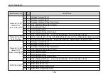
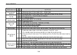
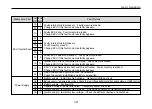
Page 251: ...irmed Flicker code ABS warning indications inform you of faults and indicate them by flickering Flicker code within ECU are used for indicating two types of flicker code Composition code It shows syst...

Page 252: ...2 flickering in the seconds section It will shut down when Faulty Diagnosis button is pressed while the composition code is flickering System composition code table 7 62 FAULTY DIAGNOSIS System Compos...

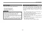
Page 253: ...s with Faulty Diagnosis code table If more than two faults are found the next fault code will activated about 4 seconds later ABS ECU memory can store upto 16 faults Most recent fault will be displaye...

Page 254: ...ing check Speed sensor signal failed Speed sensor wiring disconnected or damaged The air gap is too large 0 6mm Speed sensor indication is missed out Impulse Ring damaged or contaminated Faulty sensor...

Page 255: ...r signal Impulse Ring check and adjustment Wheel bearing adjustment Wiring check Speed sensor signal failed Speed sensor wiring disconnected or damaged Release Solenoid Short Release Solenoid Short Re...

Page 256: ...d Solenoid Short Hold Solenoid Wiring Short Circuit Valve Composition Error Valve System Wiring ECU Composition Check Short Remove the ECU X2 Plug Valve Earthing Wire Electric power Check Wiring Repla...

Page 257: ...onstantly appears Interior of ECU is not converted to Relay Faulty memory erased Change ECU if this fault code constantly appears ECU s inner Relay permanent switch is activated Faulty memory is erase...

Page 258: ...d Warning lamp wiring short circuit or disconnected Check the warning lamp wiring Faulty wheel speed sensor which was in previous Power ON cycle The condition where the warning indication is on after...

Page 259: ...Lighted lamp means that ASR is OFF d Fault code 17 80 will flicker if you perform ABS self diagnosis at this time e ASR lamp will be turned off when you delete the fault code after completing required...

Page 260: ......
Reviews: