


ENGLISH
80
2.2.4
Utility input and output electrical connections
The inverters are equipped with 4 inputs and 2 outputs to enable a number of solutions for interface with more complex installations.
Figure 9 and Figure 10 show examples of two possible configurations of the inputs and outputs.
For the installer it is sufficient to wire the required input and output contacts and then configure the functions as necessary (see sections
6.6.13 and 6.6.14).
The +19 [Vdc] power supplies to pins 11 and 18 and J5 (18-pole terminal board) can deliver a maximum of 50
[mA].
2.2.4.1
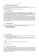
OUT 1 and OUT 2 output contacts:
The connections of the outputs listed below refer to the two 3-pole terminal boards J3 and J4 marked OUT1 and OUT 2, with a text
below indicating the type of terminal contact.
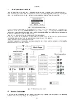
Output contact specifications
Type of contact
NO, NC, COM
Max. admissible voltage [V]
250
Max. admissible current [A]
5 -> resistive load
2,5 -> inductive load
Max. admissible cable section [mm²]
3,80
Table 8: Output contact specifications
Figure 11: Example of output connections
2.2.4.2
Input contacts (photocoupled)
The connections of the inputs listed below refer to the 18-pole terminal board J5, with numbering starting from pin 1 from the left. The
base of the terminal board also bears the text of the corresponding inputs.
-
I 1: Pins 16 and 17
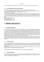
With reference to the example in Figure 9 and
using the default settings (O1 = 2: contact NO;
O2 = 2; contact NO) the following is obtained:
•
L1 lights up when the pump is blocked
(e.g. "BL": water failure block).
•
L2 lights up when the pump is running
("GO").
Summary of Contents for MCE-150/P
Page 308: ...306 IEC 60634 1...
Page 309: ...307 1 6 1 1...
Page 312: ...310 1 2 1 1 1 1 2 5 2 1 2 1 2...
Page 313: ...311 2 1 1 2 1 2 L L L 2 2 4 2 15 2 2 1 1a...
Page 314: ...312 2a 3a 4b 1b 127 240 240 480...
Page 318: ...316 GP GI 6 6 4 6 6 5 7 A B C D...
Page 323: ...321 50 60 7 DC AC 50 60 8 6 2 1 5 36 36 12 3 3 3 3 2 13 9 10 8...
Page 325: ...323 I1 F1 I1 6 6 13 2 I2 P2 6 6 13 3 I3 F3 6 6 13 4 I4 1 F4 6 6 13 5 10 GND 7 I1 I2 I3 I4...
Page 326: ...324 3 13 64 X 128 4 MODE SET 11 SET 9 MODE 1 SET 11 3 EEprom SET 6 SET MODE 3 1 11...
Page 327: ...325 3 2 1 2 3 2 1 MODE SET MODE 10 2 2 5 5 5 2 2 12...
Page 329: ...327 12 SET 14 15 13 15 3 3...
Page 331: ...329 15 14 3 4 PW 6 6 16 GO SB...
Page 332: ...330 4 4 1 Link 8 4 2 4 2 1 Link Link 15...
Page 333: ...331 17 Link 4 2 2 0 5V 4 20 A 0 4 2 2 1 FI FI 4 2 2 2 FZ 6 5 9 1 4 2 2 3 0 5 4 20 A 0 5 0...
Page 336: ...334 4 4 2 2 4 2 5 4 5 ET 6 6 9 FL 4 5 1 4 5 1 1 ET ET ET ET 0 ET 6 6 9 4 5 1 2 23 23...
Page 339: ...337 FZ FZ 2 35 FZ 37 FZ FZ FZ FZ FI 0 FZ FZ 0 5 1 7 6 GI GP FL TB...
Page 362: ...360 OC 10 6 OF 10 6 33 8 8 1 PMW 4 2 8 2 8 3 8 3 SET EE EEprom FLASH...
Page 548: ...546 IEC 364 1 inverter...
Page 549: ...547 1 Inverter inverter inverter 6 inverter 1 1...
Page 552: ...550 1 2 1 1 inverter inverter 1 1 2 5 inverter inverter 2 1 inverter inverter 2 1 2 C...
Page 554: ...552 2a 3a 4b...
Page 558: ...556 GP GI 6 6 4 6 6 5 inverter 7 A B C D...
Page 567: ...565 3 2 1 2 3 2 1 MODE SET Setpoint MODE 10 ONOMA TOY MENOY 2 Setpoint 2 5 5 5 2 2 12...
Page 571: ...569 15 15 14 3 4 Password inverter password password inverter password PW 6 6 16 GO SB FAULT...
Page 728: ...726 IEC 364 1 1...
Page 729: ...727 1 1...
Page 732: ...730 1 2 1 1 1 2 5 2 1 2 1 2 C...
Page 733: ...731 2 1 1 0 2 1 2 L L L 2 2 4 2 15 2 2 1 1...
Page 734: ...732 2a 3a 4b...
Page 738: ...736 GP GI 6 6 4 6 6 5 7 2 2 3 2 Press Flow 6 A B C D...
Page 743: ...741 DC AC 50 60 Hz 7 DC V AC 50 60 Hz Vrms V 8 6 V 2 1 5 V 36 36 12V A 3 3 3 3 2 13 8 10 8...
Page 744: ...742 12 J5 I1 11 17 16 18 16 17 I2 11 15 16 18 15 16 I3 11 14 13 18 13 14 I4 11 12 13 8 12 13 9...
Page 746: ...744 3 13 Oled 64 X 128 4 MODE SET 11 SET or 9 MODE 1 SET 10 3 EEprom SET SET or MODE...
Page 751: ...749 14 14 3 4 PW 6 6 16 GO SB FAULT...
Page 752: ...750 4 4 1 Link 8 4 2 4 2 1 Link Link 15...
Page 966: ...964 IEC 60634 1...
Page 967: ...965 1 6 1 1...
Page 970: ...968 1 2 5 2 1 2 1 2 2 1 1...
Page 971: ...969 2 1 2 L L L 2 2 4 2 15 2 2 1 1a 1a...
Page 976: ...974 3 2 2 3 2 Press Flow 6 A B C D...
Page 981: ...979 50 60 7 DC AC 50 60 8 6 2 1 5 36 36 12 3 3 3 3 2 13 2 10 8...
Page 982: ...980 5 J5 I1 11 17 16 18 16 17 I2 11 15 16 18 15 16 I3 11 14 13 18 13 14 I4 11 12 13 8 12 13 8...
Page 984: ...982 SET 9 3 EEprom SET 6 SET MODE 3 1 11 3 2 1 2 3 2 1 MODE SET MODE 10 2 2 5 5...
Page 986: ...984 4 3 2 2 12 SET 7 15 13...
Page 987: ...985 8 3 3 psi 12 GO SB BL LP HP EC...
Page 989: ...987 PW 6 6 16 4 4 1 Link 8 4 2 4 2 1 Link Link 15...
Page 993: ...991 4 4 2 2 4 2 5 4 5 ET 6 6 9 FL 4 5 1 4 5 1 1 ET ET ET ET 0 ET 6 6 9 4 5 1 2 23 23...
Page 1020: ......
Page 1021: ......
Page 1022: ......
Page 1023: ......


