


ENGLISH
93
FI
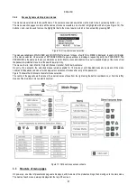
Flow sensor
FK
K factor
FD
Pipe diameter
FZ
Zero flow frequency
FT
Min. flow threshold
MP Minimum pressure pump stop due to water failure
ET
Exchange time
AC
Acceleration
NA
Number of active inverters
NC Number of simultaneous inverters
CF
Carrier frequency
TB
Dry run time
T1
Shutdown time after low pressure signal
T2
Shutdown time
GI
Integral gain
GP Proportional gain
FL Minimum Frequency
I1
Input 1 setting
I2
Input 2 setting
I3
Input 3 setting
I4
Input 4 setting
OD Type of system
PR
Pressure sensor
PW
Password Settings
4.3.1.2.1
Automatic alignment of sensitive parameters
When a multi inverter system is detected, the unit checks for consistency of the set parameters. If the sensitive parameters are not
aligned on all inverters, the display of each inverter shows a message requesting whether to transfer the configuration of the specific
inverter to the entire system. On acceptance, the sensitive parameters on the inverter where confirmation is given are distributed to all
other inverters in the series.
If there are configurations incompatible with the system, the configuration cannot be aligned from these inverters.
During normal operation, modification of a sensitive parameter on an inverter will cause automatic alignment of the parameter on all
other inverters without any request for confirmation.
Automatic alignment of sensitive parameters has no effect on all other types of parameter
.
In the particular case of inserting an inverter with default settings in the series (in the case of an inverter which replaces an existing
model or an inverter with restored factory settings), if the configurations applied, with the exception of factory settings, are consistent,
the inverter with the factory settings will automatically take on the sensitive parameters of the series.
4.3.1.3
Parameters with optional alignment
These are the parameters that are admissible even if not aligned with other inverters. Each time these parameters are modified, when
SET or MODE is pressed, the request is displayed whether to modify the entire communicating inverter series. In this way if the series
has all the same settings, the same data does not need to be set on all inverters.
List of parameters with optional alignment:
LA
Language
RC
Rated current
MS Measurement system
FS
Maximum frequency
SO
Min. dry-running factor threshold
AE
Anti-blocking
O1
Output 1 function
O2
Output 2 function
Summary of Contents for MCE-150/P
Page 308: ...306 IEC 60634 1...
Page 309: ...307 1 6 1 1...
Page 312: ...310 1 2 1 1 1 1 2 5 2 1 2 1 2...
Page 313: ...311 2 1 1 2 1 2 L L L 2 2 4 2 15 2 2 1 1a...
Page 314: ...312 2a 3a 4b 1b 127 240 240 480...
Page 318: ...316 GP GI 6 6 4 6 6 5 7 A B C D...
Page 323: ...321 50 60 7 DC AC 50 60 8 6 2 1 5 36 36 12 3 3 3 3 2 13 9 10 8...
Page 325: ...323 I1 F1 I1 6 6 13 2 I2 P2 6 6 13 3 I3 F3 6 6 13 4 I4 1 F4 6 6 13 5 10 GND 7 I1 I2 I3 I4...
Page 326: ...324 3 13 64 X 128 4 MODE SET 11 SET 9 MODE 1 SET 11 3 EEprom SET 6 SET MODE 3 1 11...
Page 327: ...325 3 2 1 2 3 2 1 MODE SET MODE 10 2 2 5 5 5 2 2 12...
Page 329: ...327 12 SET 14 15 13 15 3 3...
Page 331: ...329 15 14 3 4 PW 6 6 16 GO SB...
Page 332: ...330 4 4 1 Link 8 4 2 4 2 1 Link Link 15...
Page 333: ...331 17 Link 4 2 2 0 5V 4 20 A 0 4 2 2 1 FI FI 4 2 2 2 FZ 6 5 9 1 4 2 2 3 0 5 4 20 A 0 5 0...
Page 336: ...334 4 4 2 2 4 2 5 4 5 ET 6 6 9 FL 4 5 1 4 5 1 1 ET ET ET ET 0 ET 6 6 9 4 5 1 2 23 23...
Page 339: ...337 FZ FZ 2 35 FZ 37 FZ FZ FZ FZ FI 0 FZ FZ 0 5 1 7 6 GI GP FL TB...
Page 362: ...360 OC 10 6 OF 10 6 33 8 8 1 PMW 4 2 8 2 8 3 8 3 SET EE EEprom FLASH...
Page 548: ...546 IEC 364 1 inverter...
Page 549: ...547 1 Inverter inverter inverter 6 inverter 1 1...
Page 552: ...550 1 2 1 1 inverter inverter 1 1 2 5 inverter inverter 2 1 inverter inverter 2 1 2 C...
Page 554: ...552 2a 3a 4b...
Page 558: ...556 GP GI 6 6 4 6 6 5 inverter 7 A B C D...
Page 567: ...565 3 2 1 2 3 2 1 MODE SET Setpoint MODE 10 ONOMA TOY MENOY 2 Setpoint 2 5 5 5 2 2 12...
Page 571: ...569 15 15 14 3 4 Password inverter password password inverter password PW 6 6 16 GO SB FAULT...
Page 728: ...726 IEC 364 1 1...
Page 729: ...727 1 1...
Page 732: ...730 1 2 1 1 1 2 5 2 1 2 1 2 C...
Page 733: ...731 2 1 1 0 2 1 2 L L L 2 2 4 2 15 2 2 1 1...
Page 734: ...732 2a 3a 4b...
Page 738: ...736 GP GI 6 6 4 6 6 5 7 2 2 3 2 Press Flow 6 A B C D...
Page 743: ...741 DC AC 50 60 Hz 7 DC V AC 50 60 Hz Vrms V 8 6 V 2 1 5 V 36 36 12V A 3 3 3 3 2 13 8 10 8...
Page 744: ...742 12 J5 I1 11 17 16 18 16 17 I2 11 15 16 18 15 16 I3 11 14 13 18 13 14 I4 11 12 13 8 12 13 9...
Page 746: ...744 3 13 Oled 64 X 128 4 MODE SET 11 SET or 9 MODE 1 SET 10 3 EEprom SET SET or MODE...
Page 751: ...749 14 14 3 4 PW 6 6 16 GO SB FAULT...
Page 752: ...750 4 4 1 Link 8 4 2 4 2 1 Link Link 15...
Page 966: ...964 IEC 60634 1...
Page 967: ...965 1 6 1 1...
Page 970: ...968 1 2 5 2 1 2 1 2 2 1 1...
Page 971: ...969 2 1 2 L L L 2 2 4 2 15 2 2 1 1a 1a...
Page 976: ...974 3 2 2 3 2 Press Flow 6 A B C D...
Page 981: ...979 50 60 7 DC AC 50 60 8 6 2 1 5 36 36 12 3 3 3 3 2 13 2 10 8...
Page 982: ...980 5 J5 I1 11 17 16 18 16 17 I2 11 15 16 18 15 16 I3 11 14 13 18 13 14 I4 11 12 13 8 12 13 8...
Page 984: ...982 SET 9 3 EEprom SET 6 SET MODE 3 1 11 3 2 1 2 3 2 1 MODE SET MODE 10 2 2 5 5...
Page 986: ...984 4 3 2 2 12 SET 7 15 13...
Page 987: ...985 8 3 3 psi 12 GO SB BL LP HP EC...
Page 989: ...987 PW 6 6 16 4 4 1 Link 8 4 2 4 2 1 Link Link 15...
Page 993: ...991 4 4 2 2 4 2 5 4 5 ET 6 6 9 FL 4 5 1 4 5 1 1 ET ET ET ET 0 ET 6 6 9 4 5 1 2 23 23...
Page 1020: ......
Page 1021: ......
Page 1022: ......
Page 1023: ......


