


ENGLISH
95
After the anti-stagnant interval, if the inverter is configured as reserve, it is set to minimum priority to avoid premature wear.
4.5.2
Reserves and number of inverters involved in pumping
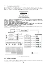
The multi inverter system reads how many elements are connected in communicating mode and calls this number N.
Then, on the basis of parameters NA and NC it decides how many and which inverters must work at a given time. NA represents the
number of inverters involved in pumping NC represents the maximum number of
inverters that can run simultaneously.
In a series, if there are NA active inverters and NC simultaneous inverters, when NC is less than NA, this means that a maximum of
NC inverters will start up simultaneously, and these will switch between NA elements. If an inverter is configured with reserve priority,
it will set as last in the starting order, therefore for example, if there are 3 inverters and one of these is configured as reserve, the
reserve unit will start in third place; otherwise if set to NA=2 the reserve will not start up unless one of the two active units sets to fault
status.
See also the explanation of parameters
NA: Inverter attivi par. 6.6.8.1;
NC: Inverter contemporanei par. 6.6.8.2;
IC: Configurazione della riserva 6.6.8.3.
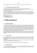
5.
POWER-UP AND START-UP
5.1
Initial power-up operations
On correct completion of installation of the hydraulic and electrical system (see chapter 2 INSTALLAZIONE) and after reading the
entire manual, the inverter can be powered up. Only in the case of initial power-up, after the initial presentation, the display shows the
error condition "EC" with the message informing the user to set the parameters required for control of the electric pump; the inverter
does not start up. To unlock the unit, simply set the rated current value [A] of the electric pump used. Before start-up, if the system
pump requires special settings, other than the default versions (see par. 8.2) first make the modifications required and then set the
rated current value, to ensure start-up with the correct settings. The parameters can be set at any time, but it is recommended to follow
this procedure when the application is in operating conditions that may impair integrity of the system components, such as in the case
of pumps with a minimum frequency limit or do not tolerate certain dry running times etc.
The following steps apply both in the case of systems with a single inverter and multi-inverter systems. In the case of multi inverter
systems, the relative connections of sensors and communication cables must be made, after which one inverter at a time must be
activated, performing the initial power-procedure for each. Once all inverters are configured, all multi-inverter system elements can be
powered up.
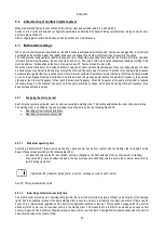
5.1.1
Rated current settings
From the page displaying the message EC, or more in general from the main menu, access the Installer menu by pressing and holding
the buttons “MODE” & “SET” & “- ” simultaneously until “RC” appears on display. In these conditions, b and – enable
respectively increase and decrease of the parameter value. Set the current as specified in the manual or on the electric pump dataplate
(for example 8.0 A).
After setting the RC value and enabling it by pressing SET or MODE, if all elements have been installed correctly, the inverter starts
up the pump (unless error, blocking or protection conditions do not occur).
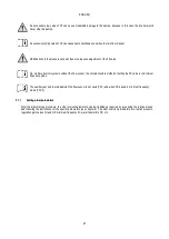
CAUTION: THE INVERTER STARTS UP THE PUMP AS SOON AS THE
RC
PARAMETER HAS BEEN SET.
5.1.2
Rated frequency settings
From the installer menu (if the RC value has just been entered, this is the same page; otherwise access as described in the above
section 5.1.1) press MODE and scroll through the menus to FN. Set the frequency using b and - as specified in the manual or
on the electric pump dataplate (for example 50 [Hz]).
Summary of Contents for MCE-150/P
Page 308: ...306 IEC 60634 1...
Page 309: ...307 1 6 1 1...
Page 312: ...310 1 2 1 1 1 1 2 5 2 1 2 1 2...
Page 313: ...311 2 1 1 2 1 2 L L L 2 2 4 2 15 2 2 1 1a...
Page 314: ...312 2a 3a 4b 1b 127 240 240 480...
Page 318: ...316 GP GI 6 6 4 6 6 5 7 A B C D...
Page 323: ...321 50 60 7 DC AC 50 60 8 6 2 1 5 36 36 12 3 3 3 3 2 13 9 10 8...
Page 325: ...323 I1 F1 I1 6 6 13 2 I2 P2 6 6 13 3 I3 F3 6 6 13 4 I4 1 F4 6 6 13 5 10 GND 7 I1 I2 I3 I4...
Page 326: ...324 3 13 64 X 128 4 MODE SET 11 SET 9 MODE 1 SET 11 3 EEprom SET 6 SET MODE 3 1 11...
Page 327: ...325 3 2 1 2 3 2 1 MODE SET MODE 10 2 2 5 5 5 2 2 12...
Page 329: ...327 12 SET 14 15 13 15 3 3...
Page 331: ...329 15 14 3 4 PW 6 6 16 GO SB...
Page 332: ...330 4 4 1 Link 8 4 2 4 2 1 Link Link 15...
Page 333: ...331 17 Link 4 2 2 0 5V 4 20 A 0 4 2 2 1 FI FI 4 2 2 2 FZ 6 5 9 1 4 2 2 3 0 5 4 20 A 0 5 0...
Page 336: ...334 4 4 2 2 4 2 5 4 5 ET 6 6 9 FL 4 5 1 4 5 1 1 ET ET ET ET 0 ET 6 6 9 4 5 1 2 23 23...
Page 339: ...337 FZ FZ 2 35 FZ 37 FZ FZ FZ FZ FI 0 FZ FZ 0 5 1 7 6 GI GP FL TB...
Page 362: ...360 OC 10 6 OF 10 6 33 8 8 1 PMW 4 2 8 2 8 3 8 3 SET EE EEprom FLASH...
Page 548: ...546 IEC 364 1 inverter...
Page 549: ...547 1 Inverter inverter inverter 6 inverter 1 1...
Page 552: ...550 1 2 1 1 inverter inverter 1 1 2 5 inverter inverter 2 1 inverter inverter 2 1 2 C...
Page 554: ...552 2a 3a 4b...
Page 558: ...556 GP GI 6 6 4 6 6 5 inverter 7 A B C D...
Page 567: ...565 3 2 1 2 3 2 1 MODE SET Setpoint MODE 10 ONOMA TOY MENOY 2 Setpoint 2 5 5 5 2 2 12...
Page 571: ...569 15 15 14 3 4 Password inverter password password inverter password PW 6 6 16 GO SB FAULT...
Page 728: ...726 IEC 364 1 1...
Page 729: ...727 1 1...
Page 732: ...730 1 2 1 1 1 2 5 2 1 2 1 2 C...
Page 733: ...731 2 1 1 0 2 1 2 L L L 2 2 4 2 15 2 2 1 1...
Page 734: ...732 2a 3a 4b...
Page 738: ...736 GP GI 6 6 4 6 6 5 7 2 2 3 2 Press Flow 6 A B C D...
Page 743: ...741 DC AC 50 60 Hz 7 DC V AC 50 60 Hz Vrms V 8 6 V 2 1 5 V 36 36 12V A 3 3 3 3 2 13 8 10 8...
Page 744: ...742 12 J5 I1 11 17 16 18 16 17 I2 11 15 16 18 15 16 I3 11 14 13 18 13 14 I4 11 12 13 8 12 13 9...
Page 746: ...744 3 13 Oled 64 X 128 4 MODE SET 11 SET or 9 MODE 1 SET 10 3 EEprom SET SET or MODE...
Page 751: ...749 14 14 3 4 PW 6 6 16 GO SB FAULT...
Page 752: ...750 4 4 1 Link 8 4 2 4 2 1 Link Link 15...
Page 966: ...964 IEC 60634 1...
Page 967: ...965 1 6 1 1...
Page 970: ...968 1 2 5 2 1 2 1 2 2 1 1...
Page 971: ...969 2 1 2 L L L 2 2 4 2 15 2 2 1 1a 1a...
Page 976: ...974 3 2 2 3 2 Press Flow 6 A B C D...
Page 981: ...979 50 60 7 DC AC 50 60 8 6 2 1 5 36 36 12 3 3 3 3 2 13 2 10 8...
Page 982: ...980 5 J5 I1 11 17 16 18 16 17 I2 11 15 16 18 15 16 I3 11 14 13 18 13 14 I4 11 12 13 8 12 13 8...
Page 984: ...982 SET 9 3 EEprom SET 6 SET MODE 3 1 11 3 2 1 2 3 2 1 MODE SET MODE 10 2 2 5 5...
Page 986: ...984 4 3 2 2 12 SET 7 15 13...
Page 987: ...985 8 3 3 psi 12 GO SB BL LP HP EC...
Page 989: ...987 PW 6 6 16 4 4 1 Link 8 4 2 4 2 1 Link Link 15...
Page 993: ...991 4 4 2 2 4 2 5 4 5 ET 6 6 9 FL 4 5 1 4 5 1 1 ET ET ET ET 0 ET 6 6 9 4 5 1 2 23 23...
Page 1020: ......
Page 1021: ......
Page 1022: ......
Page 1023: ......


