D-Link DXS-1210 Series User Manual
78
From Port / To Port:
Select the range of ports to be configured.
Queue ID:
Select the queue ID value. The range is between 0 and 7.
WRR Weight (0-127):
Enter the WRR weight value. The value is between 0 and 127.
WDRR Quantum (0-127):
Enter the WRR quantum value. The value is between 0 and 127.
Click the
Apply
button to save your settings.
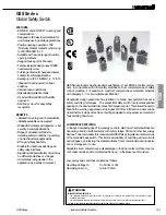
QoS > CoS to Queue Mapping
The CoS to Queue Mapping page allows you to view and configure the CoS-to-Queue mapping settings.
Figure 4.132 – QoS > CoS to Queue Mapping
Queue ID:
Select the queue ID that will be mapped to the corresponding CoS value. The value is from are 0
to 7.
Click the
Apply
button to save your settings.
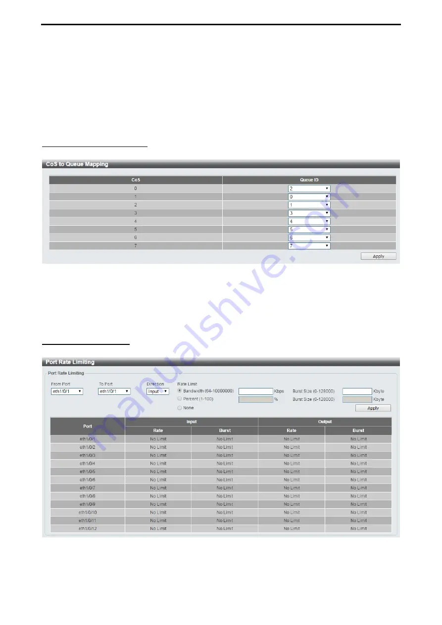
QoS > Port Rate Limiting
The Port Rate Limiting page allows you to view and configure the port rate limiting settings.
Figure 4.133 – QoS > Port Rate Limiting
From Port / To Port:
Select the range of ports to be configured.
Direction:
Select the direction. Available options are
Input
and
Output
. When
Input
is selected, the rate