Chapter 3. Using Your ATS
3.3
Finding a Target
The camera in the teaching wafer captures live video from within the semiconductor process
equipment. An image processor in the wafer reports the coordinates (X, Y, Z) of the teaching
wafer in relation to a target on the equipment. When you tell ATS to find the target, the
TeachView application displays the coordinates.
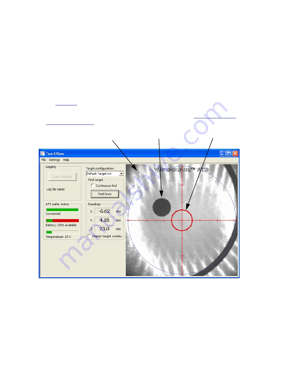
In the video image displayed in TeachView, the center of the field of view for the teaching
wafer is indicated by red cross hairs that span the length and width of the video image
(see
). A red circle is centered on the cross hairs and serves as a sight ring for aligning
the target image. When the target is within the sight ring, the equipment is aligned within the
specified tolerances. For more information on setting tolerances, see
.
Figure 3.1: The TeachView Application
Target
Live video
image
Sight ring


