8
II. Boiler Assembly
A.
Remove Crate
1. Remove all fasteners at crate skid.
2. Lift outside container and remove with all other
inside protective spacers and bracing.
B.
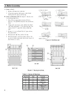
Remove boiler from skid.
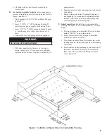
See Figure 2. Exercise care
to avoid dropping boiler.
1. Place boiler in approximate location. Refer to
Section I: Pre-Installation. Remove base hold down
bolts.
2. Using pry bar under rear corner of Base End Panel,
raise boiler and install 1½” wood blocks under rear
corners. Install ¾” pipe roller between Base and
skid.
3. Remove 1½” wood blocks. Place 3” pipe roller on
floor behind skid.
4. Roll boiler off skid. Move skid out of way.
5. Roll boiler until 3” roller is located as shown. Use
pry bar to install wood blocks under front corners of
base. Remove 3” roller.
Figure 2: Skid Removal
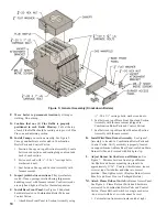
Tapping
Size
Purpose
A
2”
Supply
B
2”
Return
C
3/4”
Relief Valve
D
3/4”
Limit
E
3/4”
Auxiliary Limit
F
3/4”
Washout
G
3/4”
Drain
Table 3: Purpose of Tappings
Figure 3: Tapping Locations
Summary of Contents for 16H-340
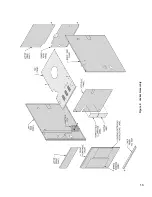
Page 13: ...13 Figure 8 Jacket Assembly ...
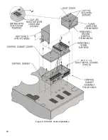
Page 14: ...14 Figure 9 EP CSD 1 Control Installation ...
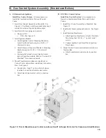
Page 16: ...16 Figure 11 Main Gas Piping Intermittent Ignition EI ...
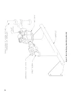
Page 17: ...17 Figure 12 Schematic Pilot Piping Honeywell EI USA ...
Page 18: ...18 Figure 15 Schematic Gas Piping EP CSD 1 Control System 16H 410 16H 505 ...
Page 37: ...37 Figure 41 Operating Instructions EI ...
Page 47: ...47 Honeywell EI Trouble Shooting Guide ...
Page 48: ...48 THIS PAGE LEFT BLANK INTENTIONALLY ...
Page 58: ...58 ...
Page 60: ...60 ...

