24
Length
(Feet)
0.3 Inch w.c. Pressure Drop
0.5 Inch w.c. Pressure Drop
½
¾
1
1¼
½
¾
1
1¼
10
132
278
520
1,050
175
360
680
1,400
20
92
190
350
730
120
250
465
950
30
73
152
285
590
97
200
375
770
40
63
130
245
500
82
170
320
660
50
56
115
215
440
73
151
285
580
60
50
105
195
400
66
138
260
530
70
46
96
180
370
61
125
240
490
80
43
90
170
350
57
118
220
460
90
40
84
160
320
53
110
205
430
100
38
79
150
305
50
103
195
400
Table 6: Maximum Capacity of Schedule 40 Pipe in CFH for Gas Pressures of 0.5 psig or Less
Table 7: Equivalent Lengths of Standard Pipe Fittings & Valves
Pipe
Size
I.D.
(Inches)
Valves (Fully Open)
Threaded Fittings
Gate
Globe
Angle
Swing
Check
90°
Elbow
45°
Elbow
90° Tee, Flow
Through Run
90° Tee, Flow
Through Branch
½”
0.622
0.35
18.6
9.3
4.3
1.6
0.78
1.0
3.1
¾”
0.824
0.44
23.1
11.5
5.3
2.1
0.97
1.4
4.1
1”
1.049
0.56
29.4
14.7
6.8
2.6
1.23
1.8
5.3
1¼”
1.380
0.74
38.6
19.3
8.9
3.5
1.6
2.3
6.9
Specific
Gravity
Correction
Factor
Specific
Gravity
Correction
Factor
0.50
1.10
1.30
1.07
0.55
1.04
1.40
1.04
0.60
1.00
1.50
1.00
0.65
0.96
1.60
0.97
0.70
0.93
1.70
0.94
0.75
0.90
---
---
0.80
0.87
---
---
Table 8: Specific Gravity Correction Factors
WARNING
Do not use matches, candles, open flames, or
other ignition source.
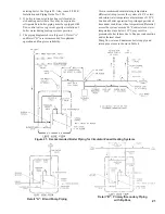
Figure 22: Recommended Gas Piping
C.
Pressure Test.
The boiler and its gas connection must
be leak tested before placing boiler in operation.
1. Protect boiler gas valve. For all testing over ½ psig,
boiler and its individual shut-off valve must be
disconnected from gas supply piping. For testing at
½ psig or less, isolate boiler from gas supply piping
by closing boiler’s individual manual shut-off valve.
2. Locate leaks using approved combustible gas
detector, soap and water, or similar nonflammable
solution.
Summary of Contents for 16H-340
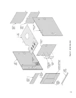
Page 13: ...13 Figure 8 Jacket Assembly ...
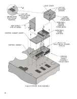
Page 14: ...14 Figure 9 EP CSD 1 Control Installation ...
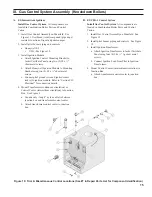
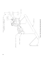
Page 16: ...16 Figure 11 Main Gas Piping Intermittent Ignition EI ...
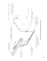
Page 17: ...17 Figure 12 Schematic Pilot Piping Honeywell EI USA ...
Page 18: ...18 Figure 15 Schematic Gas Piping EP CSD 1 Control System 16H 410 16H 505 ...
Page 37: ...37 Figure 41 Operating Instructions EI ...
Page 47: ...47 Honeywell EI Trouble Shooting Guide ...
Page 48: ...48 THIS PAGE LEFT BLANK INTENTIONALLY ...
Page 58: ...58 ...
Page 60: ...60 ...

