38
81460284R4
4. Rotate gas control knob clockwise from "ON"
C. Use only your hand to push in or turn the gas control
knob. Never use tools. If the knob will not push in or
TO TURN OFF GAS TO APPLIANCE
2. Turn off all electric power to the appliance if service is
1. Set the thermostat to the lowest setting.
to be performed.
3. Remove front door.
position to "OFF". Make sure knob rests against stop.
OPERATING INSTRUCTIONS
FOR YOUR SAFETY READ BEFORE OPERATING
2. Set the thermostat to lowest setting.
1. STOP! Read the safety information above on this label.
3. Turn off all electric power to the appliance.
A. This appliance is equipped with an ignition device
which automatically lights the pilot. Do not try to light
B. smell all around the appliance area
for gas. Be sure to smell next to the floor because some
gas is heavier than air and will settle on the floor.
BEFORE OPERATING
the pilot by hand.
WARNING:
9. Rotate gas control knob clockwise from "ON"
position to "OFF". Make sure knob rests against stop.
10. Wait five (5) minutes to clear out any gas. Then smell
under water.
water. Immediately call a qualified service technician
to inspect the appliance and to replace any part of the
control system and any gas control which has been
D. Do not use this appliance if any part has been under
turn by hand, don't try to repair it, call a qualified
service technician. Force or attempted repair may
result in a fire or explosion.
WHAT TO DO IF YOU SMELL GAS:
Do not touch any electric switch; do not use any
phone. Follow the gas supplier's instructions.
Immediately call your gas supplier from a neighbor's
If you cannot reach your gas supplier, call the
Do not try to light any appliance.
phone in your building.
fire department.
causing property damage, personal injury, or loss of life.
If you do not follow these instructions exactly, a fire or explosion may result
for gas, including near the floor. If you smell gas,
STOP! Follow "B" in the safety information above on
this label. If you do not smell gas, go to the next step.
14. EP SYSTEM
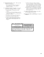
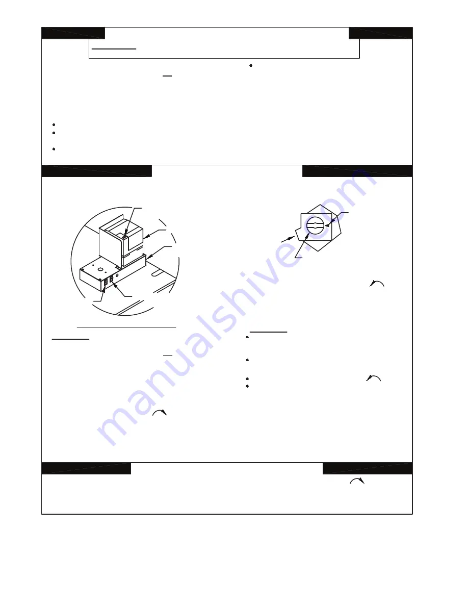
See control location diagram. On the electronic control
5. Close manual pilot valve (CSD-1 Boilers Only).
4. EP SYSTEM: Flip both rocker switches to "O" position (off).
5. This appliance is equipped with an ignition device
which automatically lights the pilot. Do not try to light
the pilot by hand.
6. Remove front door.
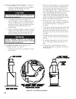
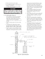
is the knob located on top of the gas valve (see diagram
supply pipe going into the boiler. The gas control knob
8. Locate the gas control valve at the end of the gas
to right).
ON
OFF
POSITION
INDICATOR
GAS
INLET
GAS CONTROL KNOB
SHOWN IN "OFF" POSITION
panel, flip the main power rocker switch to "l" position
(on). The "POWER" status indicator will light.
The pilot will light electronically. If pilot failure occurs,
the "ALARM" indicator will light. In case of pilot
failure, proceed to step 11.
Turn gas control knob counterclockwise to "ON".
On the electronic control panel, flip the main gas valve
rocker switch to "l" position (on). The "MAIN" gas valve
indicator will light. Main burners will operate.
"MAIN" gas valve indicator will cycle on and off at the
same time as the thermostat or operating control and
the main burners.
15. Replace front door.
11. Turn gas control knob counterclockwise from
"OFF" to "PILOT". When the proper position is reached
the gas control knob will pop up.
12. Turn on all electric power to the appliance.
13. Set the thermostat or operating control to desired
setting.
16. If the appliance will not operate, follow the instructions
"TO TURN OFF GAS TO APPLIANCE" and call your
service technician or gas supplier.
PILOT
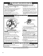
CONTROL LOCATION DIAGRAM
RM7890A
RESET SAFETY
SWITCH BUTTON
ELECTRONIC
CONTROL
PANEL
MAIN GAS ROCKER
SWITCH
MAIN POWER
ROCKER
SWITCH
7. Open manual pilot valve (CSD-1 Boilers Only).
6. Replace front door.
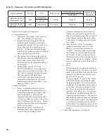
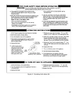
Figure 43: Operating Instructions (EP-CSD-1)
Summary of Contents for 16H-340
Page 13: ...13 Figure 8 Jacket Assembly ...
Page 14: ...14 Figure 9 EP CSD 1 Control Installation ...
Page 16: ...16 Figure 11 Main Gas Piping Intermittent Ignition EI ...
Page 17: ...17 Figure 12 Schematic Pilot Piping Honeywell EI USA ...
Page 18: ...18 Figure 15 Schematic Gas Piping EP CSD 1 Control System 16H 410 16H 505 ...
Page 37: ...37 Figure 41 Operating Instructions EI ...
Page 47: ...47 Honeywell EI Trouble Shooting Guide ...
Page 48: ...48 THIS PAGE LEFT BLANK INTENTIONALLY ...
Page 58: ...58 ...
Page 60: ...60 ...


