62
Item
No.
Description
Part No.
Quantity
16H-340
16H-410
16H-460
16H-505
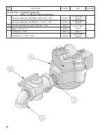
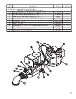
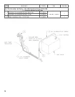
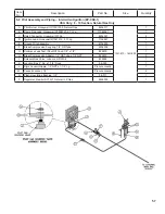
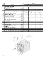
7. Trim and Miscellaneous Controls
A
Limit, 140-220°F, Honeywell
L4080D1218 (EI)
L4080B1212 (EP)
35-3300
80160474
1
1
1
1
Immersion Well, ¾” NPT x 1½” Insul. Depth
35-1010
1
1
1
1
B
Limit, Manual Reset, Honeywell L4006E1133
3503101
Optional on EI,
Standard on
EP-CSD-1
Optional on EI,
Standard on
EP-CSD-1
Optional on EI,
Standard on
EP-CSD-1
Optional on EI,
Standard on
EP-CSD-1
B1
Immersion Well, ¾” NPT x 3” Insul. Depth
35-1020
1
1
1
1
C
Temperature - Pressure Gauge
95-069
1
1
1
1
C1
Nipple, 2 NPT x 10” w/Gauge Tapping
950210
1
1
1
1
D
Safety Relief Valve, ¾ NPT, 50 psi
81660302
1
1
1
1
D1
Nipple, ¾ NPT x 3½”
Procure
Locally
1
1
1
1
E
Drain Valve, ¾ NPT, Conbraco 35-302-03
95-041
1
1
1
1
E1
Nipple, ¾ NPT x 3½”
Procure
Locally
1
1
1
1
E2
Coupling, ¾ NPT
95-056
1
1
1
1
F
Blocked Vent Switch Replacement Assembly
6016058
1
1
1
1
G
Flame Roll-out Switch
960122
1
1
1
1
G1
Flame Roll-out Switch Mounting Bracket
900122
1
1
1
1
H
Junction Box
96-055
1
1
1
1
J
Control Center, Honeywell R8285D5001
(Intermittent Circulation builds)
3505555
1
1
1
1
L
Ignition Module, Honeywell S8610M3009
3505020
1
1
1
1
M
Vestibule Wiring Harness, Complete with Vent Damper
Bypass Plug (EI) (Not Depicted)
81316010
1
---
---
---
81316011
---
1
1
1
Summary of Contents for 16H-340
Page 13: ...13 Figure 8 Jacket Assembly ...
Page 14: ...14 Figure 9 EP CSD 1 Control Installation ...
Page 16: ...16 Figure 11 Main Gas Piping Intermittent Ignition EI ...
Page 17: ...17 Figure 12 Schematic Pilot Piping Honeywell EI USA ...
Page 18: ...18 Figure 15 Schematic Gas Piping EP CSD 1 Control System 16H 410 16H 505 ...
Page 37: ...37 Figure 41 Operating Instructions EI ...
Page 47: ...47 Honeywell EI Trouble Shooting Guide ...
Page 48: ...48 THIS PAGE LEFT BLANK INTENTIONALLY ...
Page 58: ...58 ...
Page 60: ...60 ...


