7
rating of 1 perm or less with openings gasketed
and sealed, and
b. Weather-stripping has been added on openable
windows and doors, and
c. Caulking or sealants applied in joints around
window and door frames, between sole
plates and floors, between wall-ceiling joints,
between wall panels, at plumbing and electrical
penetrations, and at other openings.
5. For boiler located in an
unconfined space in a
building of other than unusually tight construction
,
adequate combustion and ventilation air is normally
provided by fresh air infiltration through cracks
around windows and doors.
6. For boiler located in an
unconfined space in a
building of unusually tight construction
or in
a
confined space
, provide outdoor air through
permanent opening(s) which communicate directly
or by duct with the outdoors or spaces (crawl or
attic) freely communicating with the outdoors.
Minimum dimension of air opening(s) is 3” (7.6
cm).
a. Two permanent openings: Locate one opening
within 12 inches (30.5 cm) of top of space.
Locate remaining opening within 12 inches
(30.5 cm) of bottom of space. Size each opening
per following:
i.
Direct communication with outdoors.
Minimum free area of each opening must be
1 square inch per 4,000 Btu per hour input
of all equipment in space.
ii.
Vertical ducts. Minimum free area of each
opening must be 1 square inch per 4,000
Btu per hour input of all equipment in space.
Duct cross-sectional area shall be same as
opening free area.
iii.
Horizontal ducts. Minimum free area of each
opening must be 1 square inch per 2,000
Btu per hour input of all equipment in space.
Duct cross-sectional area shall be same as
opening free area.
b. One permanent opening shall be permitted where
the boiler has clearances of at least 1” (2.5 cm)
from the sides and rear and 6” (15.2 cm) from
the front. Locate the opening within 12 inches
(30.5 cm) of top of space. Size opening per
following:
i.
Minimum free area of 1 square inch per
3,000 Btu per hour input of all equipment in
space.
ii.
Free area shall not be less than the sum
of the areas of all vent connectors in the
confined space.
Alternate method for boiler located within confined
space.
Use indoor air if two permanent openings
communicate directly with additional space(s) of
sufficient volume such that combined volume of all
spaces meet criteria for unconfined space. Size each
opening for minimum free area of 1 square inch per
1,000 Btu per hour input of all equipment in spaces,
but not less than 100 square inches.
7. Ventilation Duct Louvers and Grilles. Equip outside
openings with louvers to prevent entrance of rain
and snow, and screens to prevent entrance of insects
and rodents. Louvers and grilles must be fixed in
open position or interlocked with equipment to open
automatically before burner operation. Screens must
not be smaller than ¼ inch mesh.
Consider the blocking effect of louvers, grilles and
screens when calculating the opening size to provide
the required free area. If free area of louver or grille
is not known, assume wood louvers have 20-25
percent free area and metal louvers and grilles have
60-75 percent free area.
8. For Specially Engineered Installations. The above
requirements shall be permitted to be waived
where special engineering, consistent with good
engineering practice and approved by the authority
having jurisdiction, provides an adequate supply of
air for combustion, ventilation, and dilution of flue
gases.
WARNING
Do not install boiler where gasoline or other
flammable vapors or liquids, or sources of
hydrocarbons (i.e. bleaches, cleaners, chemicals,
sprays, paint removers, fabric softeners, etc.) are
used or stored.
NOTICE
Mis-sizing of the boiler with regard to the heating
system load will result in excessive boiler cycling
and accelerated component failure. Crown DOES
NOT warrant failures caused by mis-sized boiler
applications. DO NOT oversize the boiler to the
system. Modular/multiple boilers greatly reduce
the likelihood of boiler oversizing.
Summary of Contents for 16H-340
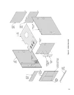
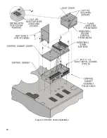
Page 13: ...13 Figure 8 Jacket Assembly ...
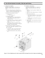
Page 14: ...14 Figure 9 EP CSD 1 Control Installation ...
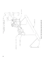
Page 16: ...16 Figure 11 Main Gas Piping Intermittent Ignition EI ...
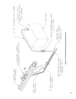
Page 17: ...17 Figure 12 Schematic Pilot Piping Honeywell EI USA ...
Page 18: ...18 Figure 15 Schematic Gas Piping EP CSD 1 Control System 16H 410 16H 505 ...
Page 37: ...37 Figure 41 Operating Instructions EI ...
Page 47: ...47 Honeywell EI Trouble Shooting Guide ...
Page 48: ...48 THIS PAGE LEFT BLANK INTENTIONALLY ...
Page 58: ...58 ...
Page 60: ...60 ...

