


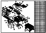


Base and bed assembly
53
51
49
57
59
47
63
65
55
67
69
71
1
75
61
3
5
7
9
11
13
15
17
19
21
23
25
27
29
31
33
35
37
39
41
43
45
73
NO.
PART NO.
PART NAME
QYT
1 V6070T-1001
Base
1
3 V6070T-1002
Oil tank
1
5 V6070T-1003
Hydraulics tank cover
1
7 V6070T-1004
Asbestos
1
9 V6070T-1051
Left side cover
1
11 V6070T-1053
Right side cover
1
13 V6070T-1055
Front cover
1
15 V6070T-1059
Rear cover
1
17 V6070T-1301
Electircal box
1
19 V6070T-1321A
HMI control panel
1
21 V6070T-2001
Bed 1
1
23 V6070T-2002
Bed 2
1
25 V6070T-2003
Bed plate 1
6
27 V6070T-2004
Bed connecting plate
1
29 V6070T-2005
Bed plate 2
4
31 V6070T-2006
Bed connecting seat
2
33 V6070T-2008
connecting plate (2)
1
35 V6070T-2012
Bed limit plate
1
37 V6070T-2021
Bed track 1
1
39 V6070T-2022
Bed track 2
1
41 V6070T-2038
Bed catchment plate
2
43 V6070T-2087
Bed cylinder ear
1
45 V6070T-2089
Bed cylinder cover
1
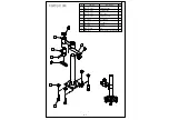
47 SVO-1012
Saw bow cylinder seat 2
49 PP-43451A
Cylinder
1
51 PP-14489A
nut
1
53 PP-14489
Connecting rod
bearing
1
55 V6068T-2088
Pin
1
57 PP-92038-01
Block
8
59 PP-92038-02
Sliding
4
61 PP-91309E
Cap screw
2
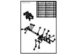
63 V6068T-2014
Bed limit stopper
1
65 V6068T-2026
T slot stopper
2
67 V6068T-2131
Stopper seat
3
69 V6068T-2133
Stopper
3
71 V6068T-2135
Handle
3
73 V6070T-2137
adjustable screw
3
75 PP-52040
plastic ball.
3
10-2
Summary of Contents for SVT-6070H
Page 2: ... ...
Page 4: ... ...
Page 10: ... ...
Page 15: ...1 5 Illustration Emergency Stop Emergency Stop ...
Page 20: ...1 10 Illustration Safety Labels ...
Page 25: ...2 3 MACHINE PARTS IDENTIFICATION ...
Page 26: ...2 4 FLOOR PLAN Machine top view Machine side view ...
Page 36: ... ...
Page 60: ... ...
Page 62: ...5 2 Fig 5 1 Control panel layout ...
Page 63: ...5 3 Fig 5 2 Circuit board layout ...
Page 64: ...5 4 Fig 5 3 Power supply layout ...
Page 65: ...5 5 Fig 5 4 PLC I O layout ...
Page 66: ... ...
Page 67: ...6 1 Section 6 HYDRAULIC SYSTEM HYDRAULIC DIAGRAM ...
Page 68: ...6 2 Fig 6 1 Hydraulic layout ...
Page 104: ... ...
Page 105: ... ...


