


4-11
No
Item
Function
Description
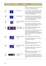
18
Right limit switch
ON/OFF
When the movable workbed feeds to the very
right end and touches the right side limit switch,
the movable workbed will stop and the green
light will come on.
19
Blade speed
Current blade speed display
20
Current table position The relative position according to the current
return-to-zero table position.
21
System parameter
setting
Press this button to set up system parameters.
Password is required.
All parameters have been set up by the
manufacturer. In order to prevent random
change from being made to these parameters
and affect cutting precision and machine life, this
function is protected with a set of password.
22
Cutting program
setting
Press this button to display cutting-related
information, e.g. blade speed.
Information and parameter setups for optional
accessories such as blade deviation detector can
also be configured in this setup page.
Refer to Cutting Display & Setup in the following
page.
23
Material cutting
reference
This 2-page reference chart lists out the required
blade speed and cutting rate for each different
material.
24
PLC monitor
Shows current PLC signals.
25
Error report
Lists a historical report of the errors and the time
of occurrence as well as provides troubleshooting
support. 6 pages in total.
26
(yellow highlight)
Error display
Displays error messages in the order of
occurrences; press the message to clear the
messages.
Error messages must be cleared for the
machine to continue to operate normally.
Summary of Contents for SVT-6070H
Page 2: ... ...
Page 4: ... ...
Page 10: ... ...
Page 15: ...1 5 Illustration Emergency Stop Emergency Stop ...
Page 20: ...1 10 Illustration Safety Labels ...
Page 25: ...2 3 MACHINE PARTS IDENTIFICATION ...
Page 26: ...2 4 FLOOR PLAN Machine top view Machine side view ...
Page 36: ... ...
Page 60: ... ...
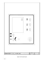
Page 62: ...5 2 Fig 5 1 Control panel layout ...
Page 63: ...5 3 Fig 5 2 Circuit board layout ...
Page 64: ...5 4 Fig 5 3 Power supply layout ...
Page 65: ...5 5 Fig 5 4 PLC I O layout ...
Page 66: ... ...
Page 67: ...6 1 Section 6 HYDRAULIC SYSTEM HYDRAULIC DIAGRAM ...
Page 68: ...6 2 Fig 6 1 Hydraulic layout ...
Page 104: ... ...
Page 105: ... ...


