


2-2
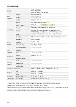
SPECIFICATION
Model
SVT-6070H
Table Moving Vertical Bandsaw
Max.
Capacity
Height
600 mm (23.6 in)
Throat
700 mm (27.6 in)
Length
1250 mm (49.2 in)
Saw Blade
Speed
15 ~ 100 m/min (50~328 ft/min)
Size (L x W x T)
6040 x 54 x 1.6 mm (237.8 x 2.13 x 0.063 in)
Pressure
38~45kgs / cm2 (Tolerance: +1~+2 kgs / cm² )
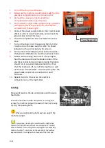
Tension
Hydraulic with automatic blade breakage detection
2400~2600kgs / cm2 (Tolerance: +100~+150 kgs / cm² )
Guide
Hydraulic controlled interchangeable tungsten carbide
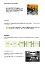
Cleaning
Steel wire brush with flexible drive shaft driven by main motor
Motor
Output
Saw Blade
10 HP (7.5 kW)
Hydraulic
2 HP (1.5 kW)
Coolant Pump
1/4 HP (0.18 kW)
Other Component
-------------------------
Tank
Capacity
Hydraulic
-------------------------
Coolant
-------------------------
Workbed
Height
1400 mm (55.1 in)
Weight Capacity
-------------------------
Feeding
Length
Mode
-------------------------
Single Stroke
-------------------------
Multi Stroke
-------------------------
Floor Space (L X W X H)
3,258 x 2,920 x 3,345 mm (128.3 x 115 x 131.7 in)
Weight
Net
4,980 KG (10,956 lb)
Gross
5,350 KG (11,770 lb)
Operating
Environment
Temperature (
゚
C)
5~40
゚
C (41~104
゚
F)
Humidity (%)
30~85% (without condensation)
*Please refer to the formula "Watt/Voltage = Amperage" with the information above.
*Design and specification are subjected to change without notice.
*The saw blade pressure and tension standard above are the general values. For special saw blade,
please contact to the saw blade manufacturer for the applicable values.
Summary of Contents for SVT-6070H
Page 2: ... ...
Page 4: ... ...
Page 10: ... ...
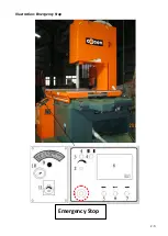
Page 15: ...1 5 Illustration Emergency Stop Emergency Stop ...
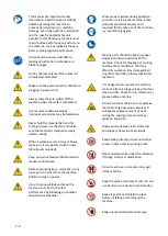
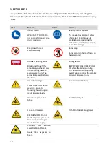
Page 20: ...1 10 Illustration Safety Labels ...
Page 25: ...2 3 MACHINE PARTS IDENTIFICATION ...
Page 26: ...2 4 FLOOR PLAN Machine top view Machine side view ...
Page 36: ... ...
Page 60: ... ...
Page 62: ...5 2 Fig 5 1 Control panel layout ...
Page 63: ...5 3 Fig 5 2 Circuit board layout ...
Page 64: ...5 4 Fig 5 3 Power supply layout ...
Page 65: ...5 5 Fig 5 4 PLC I O layout ...
Page 66: ... ...
Page 67: ...6 1 Section 6 HYDRAULIC SYSTEM HYDRAULIC DIAGRAM ...
Page 68: ...6 2 Fig 6 1 Hydraulic layout ...
Page 104: ... ...
Page 105: ... ...


