


i
NOTE:
Read this instruction manual carefully to familiarize yourself with the installation,
operation and maintenance of your COSEN bandsaw machine.
Operate the machine following the procedures described in the manual to prevent
personal injuries or machine damage.
Keep this manual handy and refer to it whenever you are uncertain of how to
perform procedures.
For technical support or parts purchase, please contact your nearest COSEN
representative or our service center:
For Europe:
email: [email protected]
phone: +31-77-7600280
fax: +31-77-7600288
web: www.cosensaws.eu
For Taiwan and other countries:
email: [email protected] .tw
phone: +886-3-5332143
fax: +886-3-5348324
web: www.cosen.com.tw
For US, Mexico, and Canada:
email: [email protected].
phone: +1-704-943-1030
toll free: +1-877-SAWING1
fax: +1-704-943-1031
web: www.cosensaws.com
For China:
email: [email protected]
phone: +86-152-50127815
web: www.cosensaws.cn
Instruction Manual: SVT-6070H
Table Moving Vertical Bandsaw
Ver. 4 2020/7/30
©
2013 by COSEN MECHATRONICS CO., LTD.
No part of this publication may be photocopied or otherwise reproduced without the prior written permission of COSEN.
Printed in Taiwan
FROM THE MANUFACTURER
Thank you for your purchase of COSEN’s bandsaw machine and your trust in the COSEN
brand.
We are excited to have you as our valued customer and look forward as much as you do to
the accelerated productivity, long-lasting endurance and superb cost-effectiveness this
machine is about to bring to you.
To ensure you are fully utilizing our machine and taking advantage of it in every possible
way, please take your time to read through this instruction manual.
Any comments or suggestions in making our services better, please do not hesitate to let us
know. Thank you again!
Summary of Contents for SVT-6070H
Page 2: ... ...
Page 4: ... ...
Page 10: ... ...
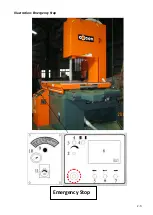
Page 15: ...1 5 Illustration Emergency Stop Emergency Stop ...
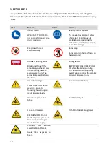
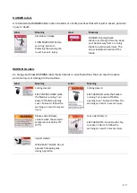
Page 20: ...1 10 Illustration Safety Labels ...
Page 25: ...2 3 MACHINE PARTS IDENTIFICATION ...
Page 26: ...2 4 FLOOR PLAN Machine top view Machine side view ...
Page 36: ... ...
Page 60: ... ...
Page 62: ...5 2 Fig 5 1 Control panel layout ...
Page 63: ...5 3 Fig 5 2 Circuit board layout ...
Page 64: ...5 4 Fig 5 3 Power supply layout ...
Page 65: ...5 5 Fig 5 4 PLC I O layout ...
Page 66: ... ...
Page 67: ...6 1 Section 6 HYDRAULIC SYSTEM HYDRAULIC DIAGRAM ...
Page 68: ...6 2 Fig 6 1 Hydraulic layout ...
Page 104: ... ...
Page 105: ... ...


