


3-9
Anchoring the machine
Normally there is no need to anchor the machine. If the machine is likely to vibrate, fix the machine
to the floor with anchor bolts.
Shock absorption steel plates are provided and can be placed under each leveling bolt to prevent
their sinking into the concrete floor.
Installing roller table (optional)
The roller table is used to support long material at
the rear and/or the front of the machine.
If you have ordered the optional roller table for
cutting long material, position it before or behind
the machine.
Level the roller table and the stand with the
machine by adjusting the leveling bolts.
Installing Fire Control Device
Install a fire extinguisher or any other fire control device in the shop in case a fire breaks out.
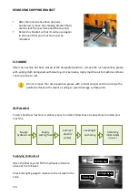
RELOCATING
We recommend you follow these procedures when relocating or shipping your machine to other
place:
1.
Descend the saw frame to its lowest position then turn off the power.
2.
Fix the saw frame using the shipping bracket that originally came with the machine.
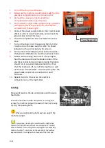
3.
If you are shipping the machine, pack the machine carefully with industrial plastic wraps to
protect it from dust.
4.
Use a crane or forklift to raise it. If a crane is used to lift the machine, ensure that the lifting
cable is properly attached to the machine.
5.
Do not forget to include the equipments originally furnished including the shock absorption
steel plates and the instruction manual.
Adjust bolts
Summary of Contents for SVT-6070H
Page 2: ... ...
Page 4: ... ...
Page 10: ... ...
Page 15: ...1 5 Illustration Emergency Stop Emergency Stop ...
Page 20: ...1 10 Illustration Safety Labels ...
Page 25: ...2 3 MACHINE PARTS IDENTIFICATION ...
Page 26: ...2 4 FLOOR PLAN Machine top view Machine side view ...
Page 36: ... ...
Page 60: ... ...
Page 62: ...5 2 Fig 5 1 Control panel layout ...
Page 63: ...5 3 Fig 5 2 Circuit board layout ...
Page 64: ...5 4 Fig 5 3 Power supply layout ...
Page 65: ...5 5 Fig 5 4 PLC I O layout ...
Page 66: ... ...
Page 67: ...6 1 Section 6 HYDRAULIC SYSTEM HYDRAULIC DIAGRAM ...
Page 68: ...6 2 Fig 6 1 Hydraulic layout ...
Page 104: ... ...
Page 105: ... ...


